03233A(E)-CHAPTER 2 10/30/03 4:00 PH Page 4
Connect another cabb
between the other OUT
termina! on the s@itter
and the A-IN terminal on
the R[ (A/B) switch.
Incoming
Cable
Splitter
RF (A/B)
Cable Box Switch
75[_
Connect the last coaxial
cable between the OUT
terminal on the R[ (A/B) Incoming
switch and the VH[!UHF Cable Splitter RF (A/B) TV Rear
terminal on tile rear of Cable Box Switch
the IV.
After yaH're made this connection, set the A/_ switch to the "A" position for noHna] view-
ing, Set the AJB switch to the "B" position to view sc{ambled channels (When you set the
/_J_ switch to '%" you will need to trine you{ TV to the cable bow oHtput charmer which is
usually channel 3 o{ 4.)
Connecting a Second VCR to Record from
the IV
You[" TV can send out signals of its pictHre and soHnd to be recoKted by a second
VCR.
To do this, connect yaH[ second VCR as folk)ws:
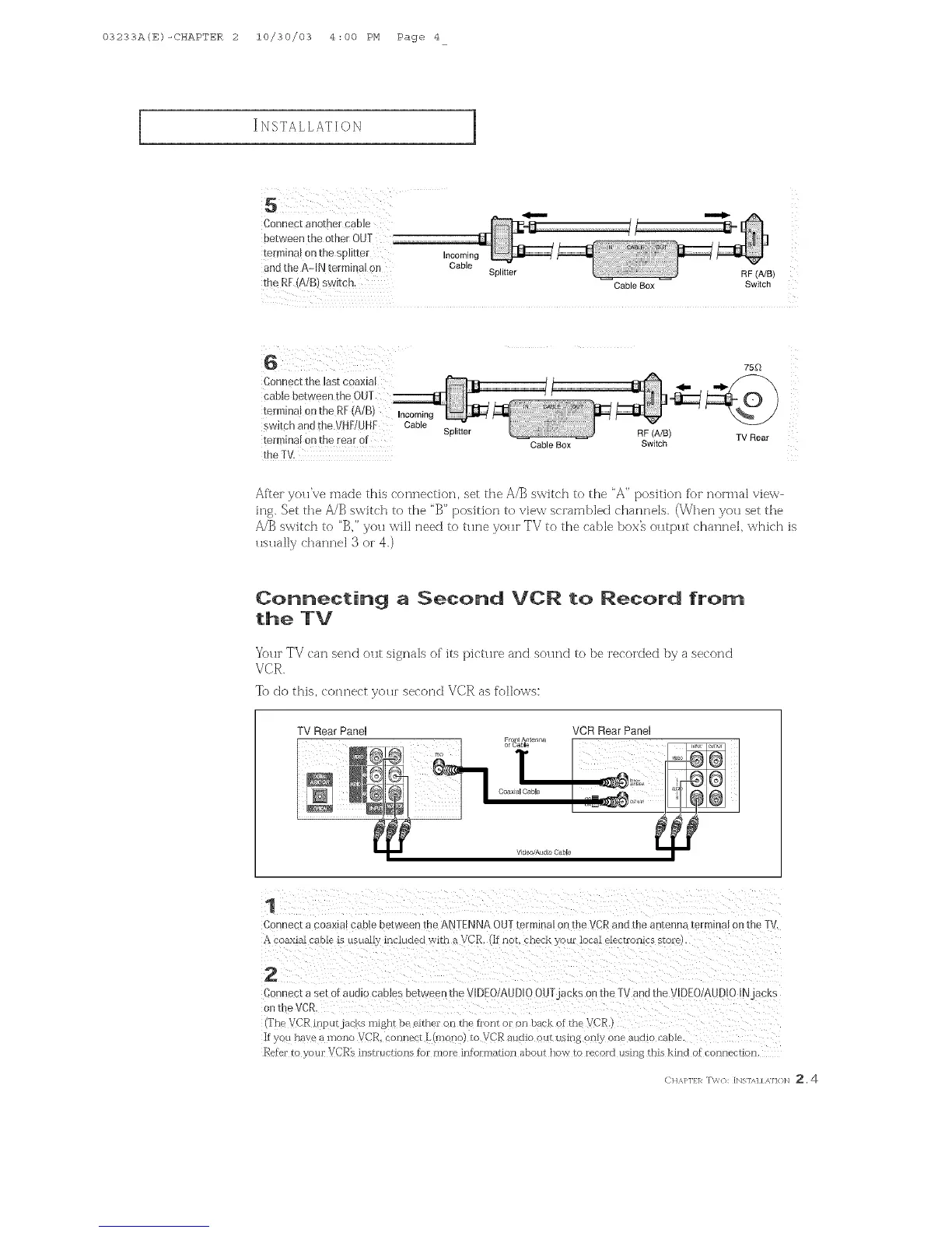
TV Rear Panel VCR Rear Panel
Fro An erma
or _laJ ble
1
Conne K a coax[m cab e between @e ANTENNA OUT/el mmm on me v }R and the antenna termmal on {meTV.
coaxml cable is HsuazIv included with a VCR, (If hal check your local ele¢ Francs state
2
Car nect a set of audio c2ates between the VIDEO/AUDIOOUTj_ cks on the ] _/and [he VIDEO/AUDIO IN _cKs
on [heVCR
@'he VCR iny ilrjac_Ls might be eithei on the hont oi on back _f the VC_
If you nave a nlono VCR. connect L(mono} to VCR audio out Lisiri 8 only one aH<UO i'aole.
Refer to your VCR% insh'ucrions tof mo_e intoHnation about now ro l_!'oKI Hsln 8 this kind of connection
CH,_J'lfl_ T\'/{]: [Ngl/q / ,MH}N _, 4