11
Λ
1-5. Installation
(1) Indoor unit (Example; 4-way cassette type)
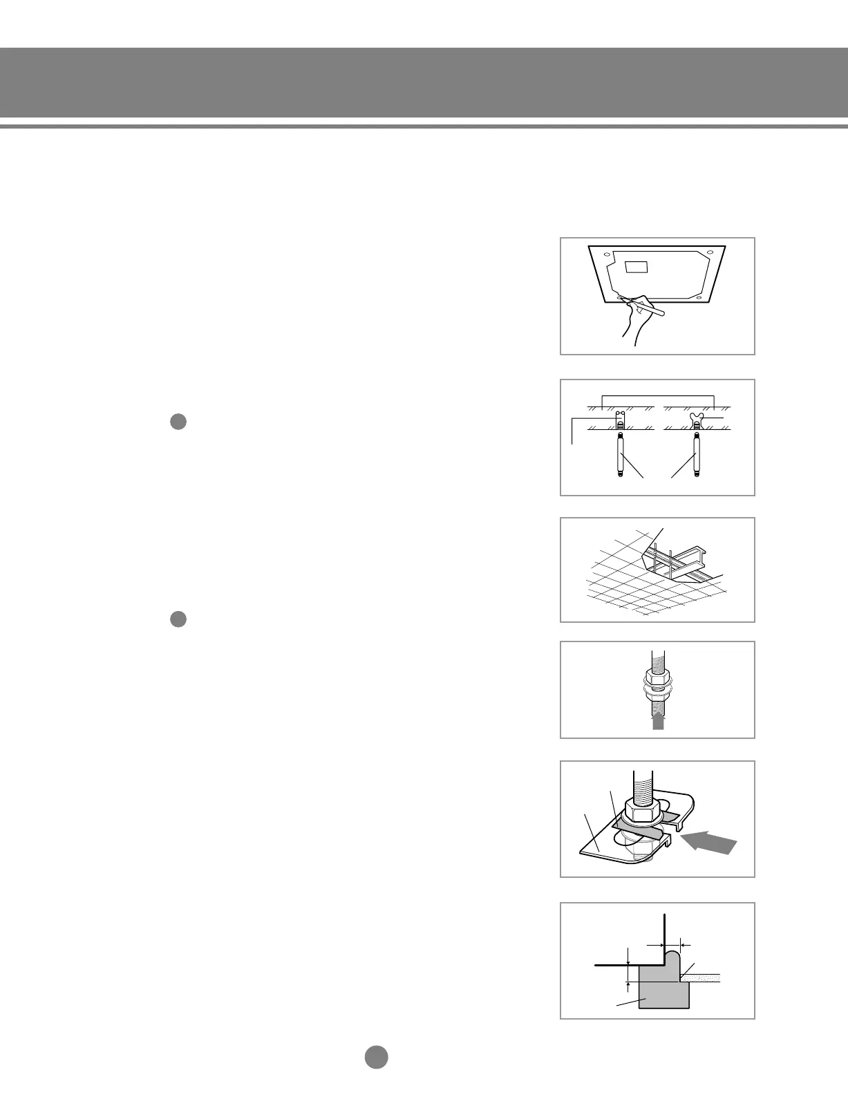
1) Place the pattern sheet on the ceiling at the spot where you
want to install the indoor unit.
2) Insert bolt anchors, use existing ceiling supports or construct
a suitable support as shown in figure.
3) Install the suspension bolts depending on the ceiling type.
4) Screw eight nuts to the suspension bolts making space for
inserting the indoor unit bracket.
5) Hang the indoor unit on the suspension bolts between two nuts.
6) Tighten the nuts to suspend the unit. Cut a pad stopper and
place it on the bracket at this time.
7) Adjust the unit to the appropriate position considering the
installation area for the front panel.
7-1 Place the pattern sheet on the indoor unit.
7-2 Adjust a space between the ceiling and the indoor unit by
using the gauge.
7-3 Fix the indoor unit securely after adjusting the level of the
unit by using a level.
7-4 Remove the pattern sheet, connect the other cables and
install the front panel.
Concrete
Suspension bolt(M8)-field supply
Hole in anchor
Hole in plug
Insert
Ceiling support
3/4”
Indoor Unit
Ceiling
Gauge of
Dimensions
5/8”
Pad stopper
Bracket
◆ Ensure that the ceiling is strong enough to support
the weight of the indoor unit. Before hanging the unit,
test the strength of each attached suspension bolt.
◆ If the length of suspension bolt is more than 5ft.,
support the unit to prevent vibration.
IMPORTANT
You must install four suspension bolts when installing
the indoor unit.
IMPORTANT
◆
Piping must be laid and connected inside the ceiling when
suspending the unit. If the ceiling is already constructed,
lay the piping into position for connection to the unit before
placing the unit inside the ceiling.
NN
NN
oo
oo
tt
tt
ee
ee
◆
For installation of another indoor unit, refer to an
appropriate installation manual.
NN
NN
oo
oo
tt
tt
ee
ee
◆ Since the diagram is made of paper, it may shrink or stretch
slightly due to temperature or humidity. For this reason,
before drilling the holes check the dimensions between the
markings.
NN
NN
oo
oo
tt
tt
ee
ee
5-1.Installation_TM_E_06890 2/27/03 10:15 AM Page 11