. Installation
Λ
7. Wiring
30
ΛΛ
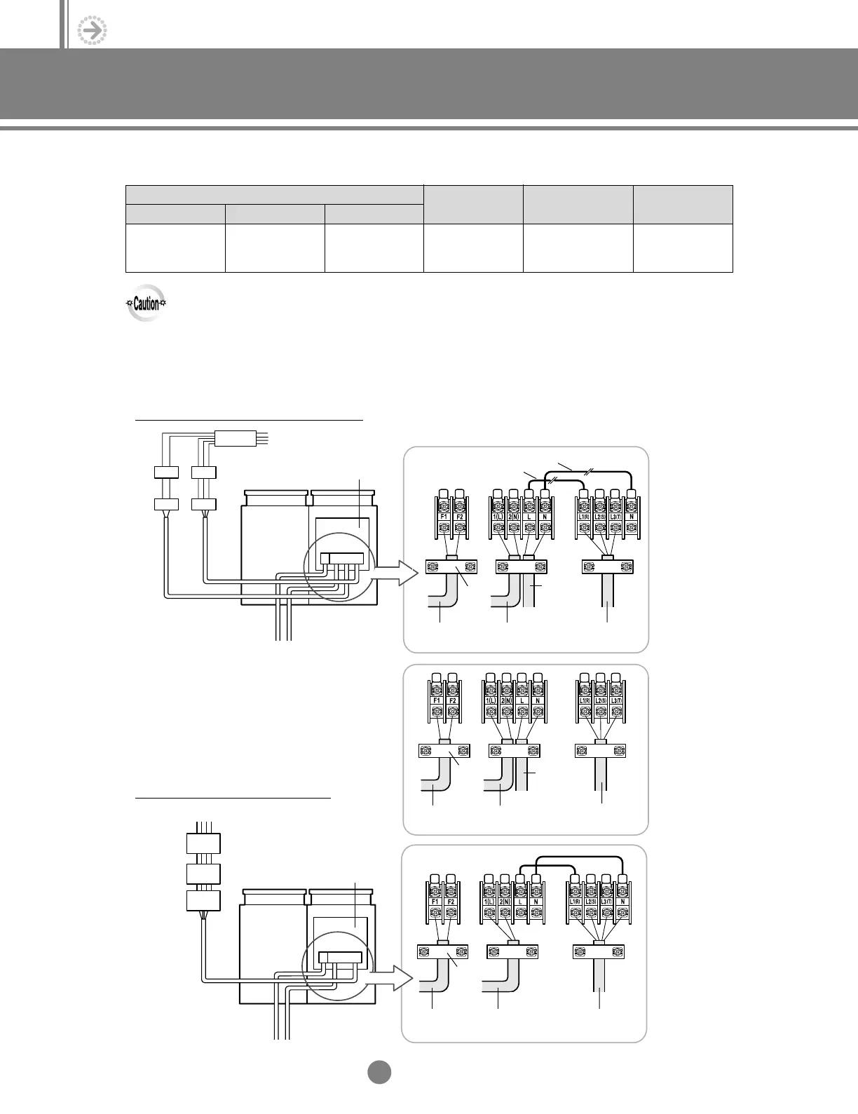
7-4. Wiring diagram
When using ELBs for 3 phase and 1 phase
When using ELB for 3 phase 4 wires
Power Supply
Electrical component box
◆
Case 1 Cut jumper wires ‘A’ and ‘B’.
◆
Case 2
Indoor Unit
Communication
Cable
Single
Phase
3 Phase
3 Wires
Connection cord 3 Phase
Power Cable
Single
Phase
AC220V
Cable
clamp
Part A
Part B
Communication
Cable
Connection cord
3 Phase
Power Cable
Single
Phase
AC220V
Cable
clamp
Power Supply
Electrical component box
Indoor Unit
Communication
Cable
3 Phase
4 Wires
Connection cord 3 Phase
Power Cable
Cable
clamp
Power supply (1 phase)
Max/Min (V) Power cablePower supply
Communication cable
(VCTF, 2wires)
Earth wire
Home server
(VCTF, 2wires)
220V / 60Hz
220-240V/50Hz
208-230V/60Hz
± 10% 0.75~1.25mm
2
0.75~1.25mm
2
1.6mm
(IV, 1wire)
2.0mm
2
(CV, 2wires)
●
The power supply cable shall be connected to the power supply terminal and shall be fixed with clamp as in the following figure.
●
Phase unbalance shall be within 2% of power supply rating.
- If the phase unbalance is high, the life of the condenser is shortened.
- If the phase unbalance exceeds 4%, the indoor unit stops and error mode displays.
7-3. Interconnect wire sizing
5-2.Installation_TM_E_06890 2/27/03 10:16 AM Page 30