ΙΙ
. Control System
4. Installation
ΙΙ
12
4-3. Centralized controller
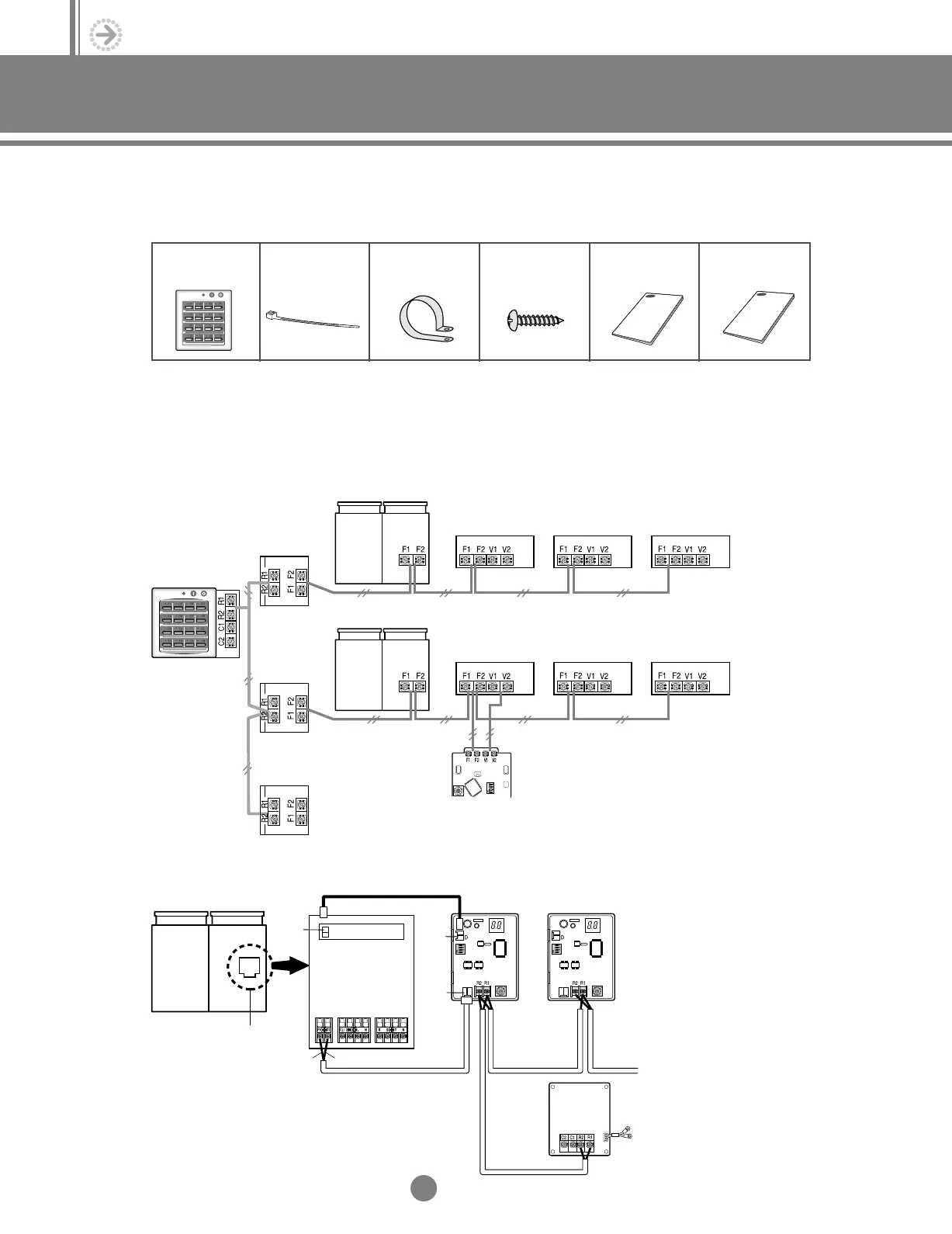
(1) Accessories
(2) Wiring diagram
Each outdoor unit connected to the same centralized controller must have its own interface module.
(3) Interface module installation
Centralized
Controller (1)
Cable-tie (2) Cable Clamp (5) M4x16 Tapped
Screw (7)
Owner’s
instructions(1)
Installation
manual(1)
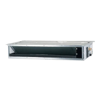
Outdoor unit 1
Interface
module 1
Interface
module 2
Interface
module 3
Centralized
controller
Indoor unit 1 Indoor unit 2 Indoor unit 3
Outdoor unit 2
Indoor unit 4
Wired remote
controller
Indoor unit 5 Indoor unit 6
◆ If you would like to install the centralized controller, you must install the optional interface module
in the outdoor unit.
NN
NN
oo
oo
tt
tt
ee
ee
Interface
module 1
Interface
module 2
CN01
(BLUE)
CN12
(BLUE)
PCB
Terminal Block
CN02
(RED)
Interface
module 3
AC power supply
Centralized
controller
Outdoor unit
Red
Blue
2.Control system_TM_E_06890 2/27/03 10:13 AM Page 12