21
Chapter 2. Device setup
External connection
Checkpoints
• Before connecting a source device, read the user manual provided with it.
The number and locations of ports on source devices may differ from device to
device.
• Connect the sound ports correctly: left = white and right = red.
• Check the types of ports at the back of the product you want to connect.
The appearance may differ depending on the product.
WARNING
Do not connect the power cable until all connections are completed.
Connecting the power cable during connection may damage the product.
Cable Connection
RS232C Cable
Interface RS232C (9 pins)
Pin TxD (No.2), RxD (No.3), GND (No.5)
Bit rate 9600 bps
Data bits 8 bit
Parity None
Stop bit 1 bit
Flow control None
Maximum length 15 m (only shielded type)
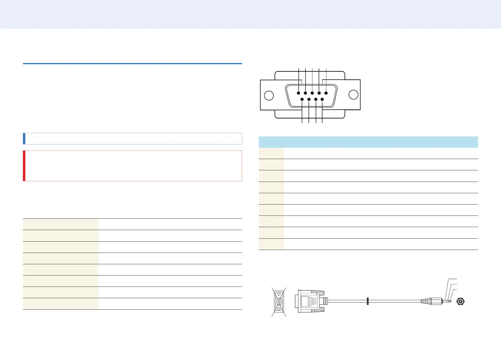
Pin assignment
1 2 3 4 5
6 7 8 9
Pin Signal
1 Detect data carrier
2 Received data
3 Transmitted data
4 Prepare data terminal
5 Signal ground
6 Prepare data set
7 Send request
8 Clear to send
9 Ring indicator
RS232C cable
• Connector: 9-Pin D-Sub to Stereo Cable
5
16
9
-P2-
1
2
3