EasyManua.ls Logo

Santerno Sinus Penta - Start-Up Menu

Santerno Sinus Penta
97 pages
Print Icon
To Next Page IconTo Next Page
To Previous Page IconTo Previous Page
Loading...
SINUS PENTA
BASIC
USER MANUAL
38/97
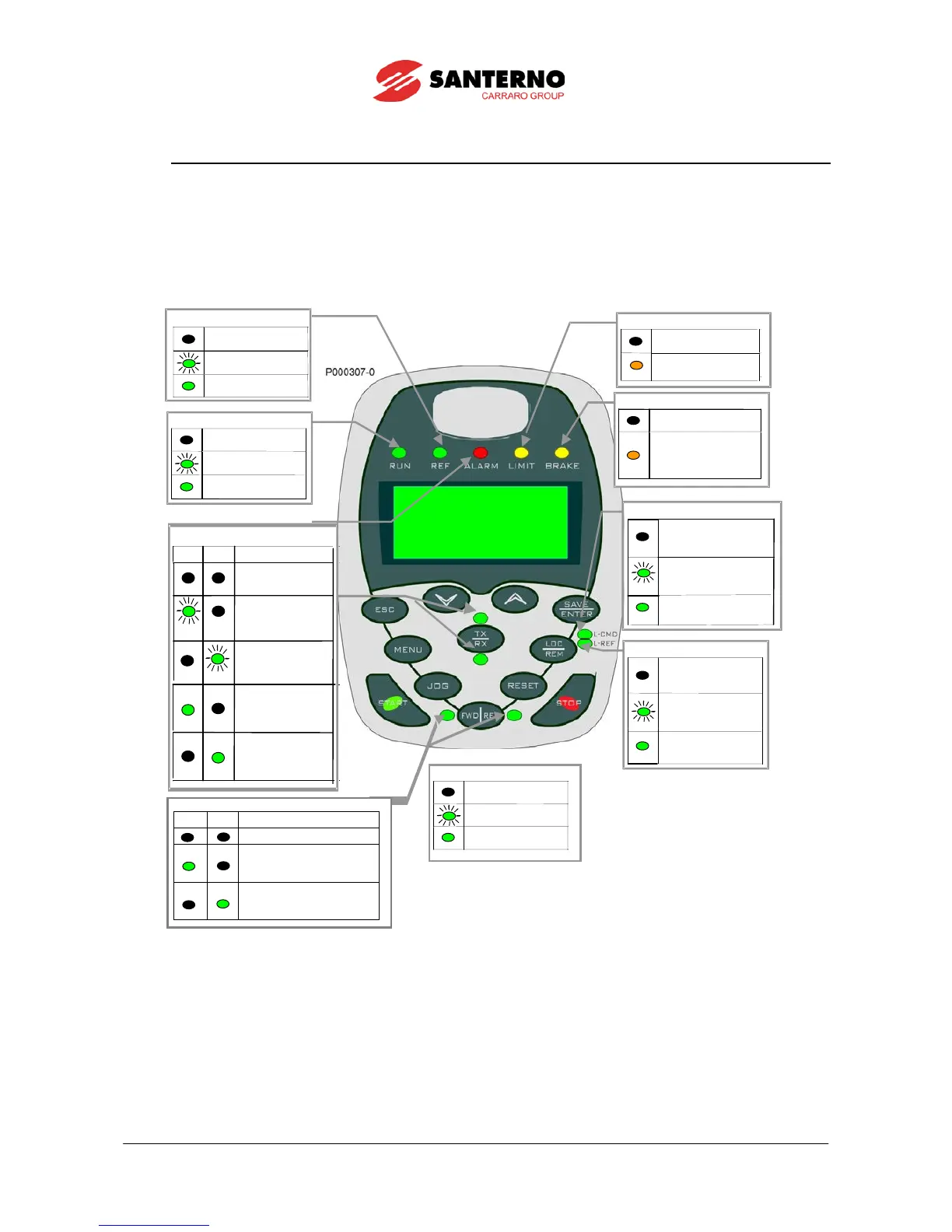
3.5. Indicator LEDs in the Display/Keypad
Eleven LEDs are located on the keypad, along with a 4-line, 16-character LCD display, a buzzer and 12 function keys. The
display shows parameter values, diagnostic messages and the variables processed by the Penta drive.
The figure below shows the location of the signal LEDs and their functionality.
RUN LED - Green
Motor not powered
Motor powered,
but no torque (idle)
Motor powered
and running
REF LED - Green
Reference for speed,
frequency or torque = 0
Motor acceleration
or deceleration
Reference on
inverter a tastiera
No active limit
Voltage or current
limit active
BRAKE LED - Yellow
Ordinary run
Either one is active:
-
DC current brake
-
IGBT braking
-
Ramp extension.
L-CMD LED – Green
Commands sent from
sources other than
keypad
Commands sent both
from keypad and
terminal board
Commands sent
from keypad only
KEY
LED off
LED flashing
LED on (fixed)
Reference sent from
sources other
than keypad
Reference sent both
from keypad and
terminal board
Reference sent from
keypad only
L-REF LED - Green
FWD and REV LEDs – Green
FWD
REV
Total reference = 0
Total reference of frequency/
speed/torque
is being sent
and is positive
Total reference of frequency/
speed/torque is being sent
and is negative.
TX and RX LEDs - Green
TX
RX
No parameter transfer
in progress
Download: waiting
for confirmation
Upload: waiting
for confirmation
Parameter
downloading from
keypad to inverter
Parameter
uploading from
inv
erter to keypad

Table of Contents

Other manuals for Santerno Sinus Penta

Related product manuals