-13-
Mechanical Disassemblies
For servicing the AV, AV Sub, Main-A and Main-D Board, it is advisable to set
up the service position for the checking and testing easily following to below
steps
1) Remove the AV, AV Sub and Main-A/D Board following to steps 1~5 of
“Mechanical Disassemblies”.
* Should be remove the Main-A Board Holder and Viewer Holder.
2) Mount the AV, AV Sub, and Main-A/D Board to the Main-B Board.
* Not necessary to connect the Viewer Board.
Note:
In the mounting, make sure of the mounting direction of connectors.
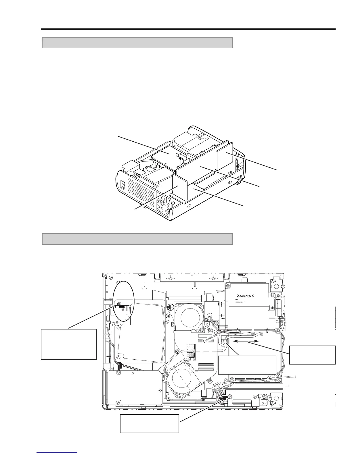
11. SERVICE POSITION
Fig.12
Main-D Board
Main-B Board
AV Board
Main-A Board
AV Sub Board
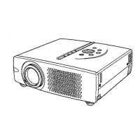
Make sure to dress the lead wires as follows when assembling the chassis
and cabinets
12. LEAD WIRE DRESSING
Fig.13
AV Sub Board
Do not loosen
these wires
Use a fixer for dress-
ing these wires.
Fix wires firmly after
dressing.
Make sure that the
wires around here
are dressed not to
touch to the fans.