-17-
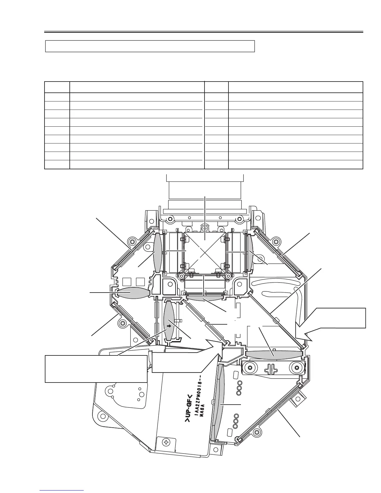
Optical Parts Disassemblies
When the optical parts mounting or assembling, the parts must be mounted
in the specified location and direction. Please refer to the figure below and
“Mounting direction of optical parts” on next page.
1 Prism ass’y
2 Relay lens (IN)
3 Relay lens (OUT)
4 Condenser lens (IN)
5 Condenser lens (OUT)
6 Condenser lens
7 Condenser lens (B)
8 Mirror (W)
9 Mirror (R)
10 Mirror (B)
11 Optical Filter (UV cut)
12 Polarized glass (R-filter)
13 Polarized glass (IN/G)
14 Polarized glass (IN/B)
15 Dichroic mirror (R)
16 Dichroic mirror (G)
No. Part name No. Part name
1
3
2
4
5
6
7
13
14
8
12
Parts Name and Locations
11
16
15
Fig.9
10
9
10
6
Printed marker
comes this side
Printed marker
comes this side
Mount lens to be the same direc-
tion of the arrow marker on both of
the lens and optical base bottom.