1) Remove 4 screws (A) and pull the Viewer and Main-A/D Board Ass’y
upward.
2) Remove 2 screws (B) and disconnect connector K1A, then take the
Viewer Board Ass’y off from the Main-A/D Board Ass’y.
3) Remove 4 screws (C) and take the Viewer Unit off from the Viewer
Mounting Holder.
4) Remove 2 screws (D) and remove the Main-D Board.
5) Remove 4 screws (E) and take the Main-A Board off from the Main-A
Board Holder.
4. VIEWER*, MAIN-A/D BOARD REMOVAL
-9-
Mechanical Disassemblies
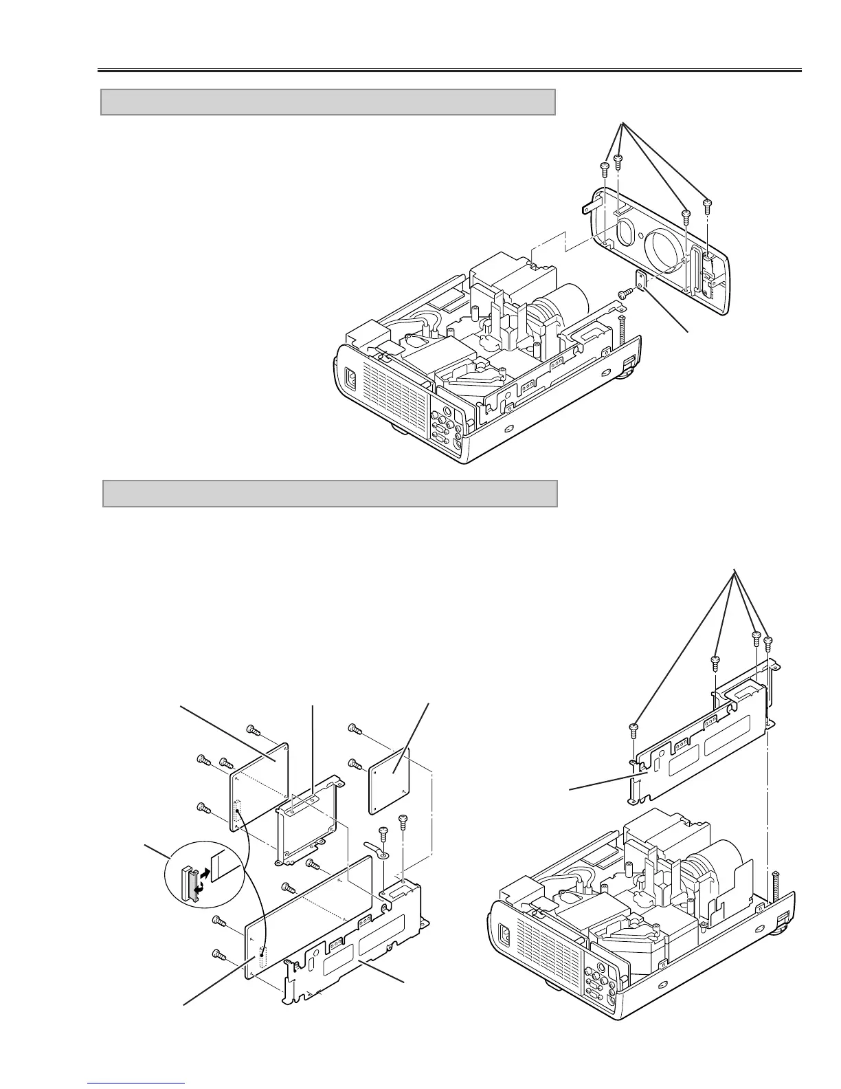
1) Remove 4 screws (A) and remove the front cabinet forward.
2) Remove a screw (B) and remove the Viewer LED Board.
* Model without the PC Card slot does not provide the Vierwer Board.
3. FRONT CABINET, VIEWER LED BOARD* REMOVAL
Fig.3
A
A
Fig.4
Fig.5
D
D
B
B
E
E
E
E
C
C
C
C
Viewer Board *
Main-D Board
K1A
Main-A Board
Viewer, Main-
A/D Ass’y
Main-A Board
Holder
Viewer Board Holder
B
Viewer LED
Board *
* Model without the PC Card slot does not
provide the Vierwer Board.