-10-
Mechanical Disassemblies
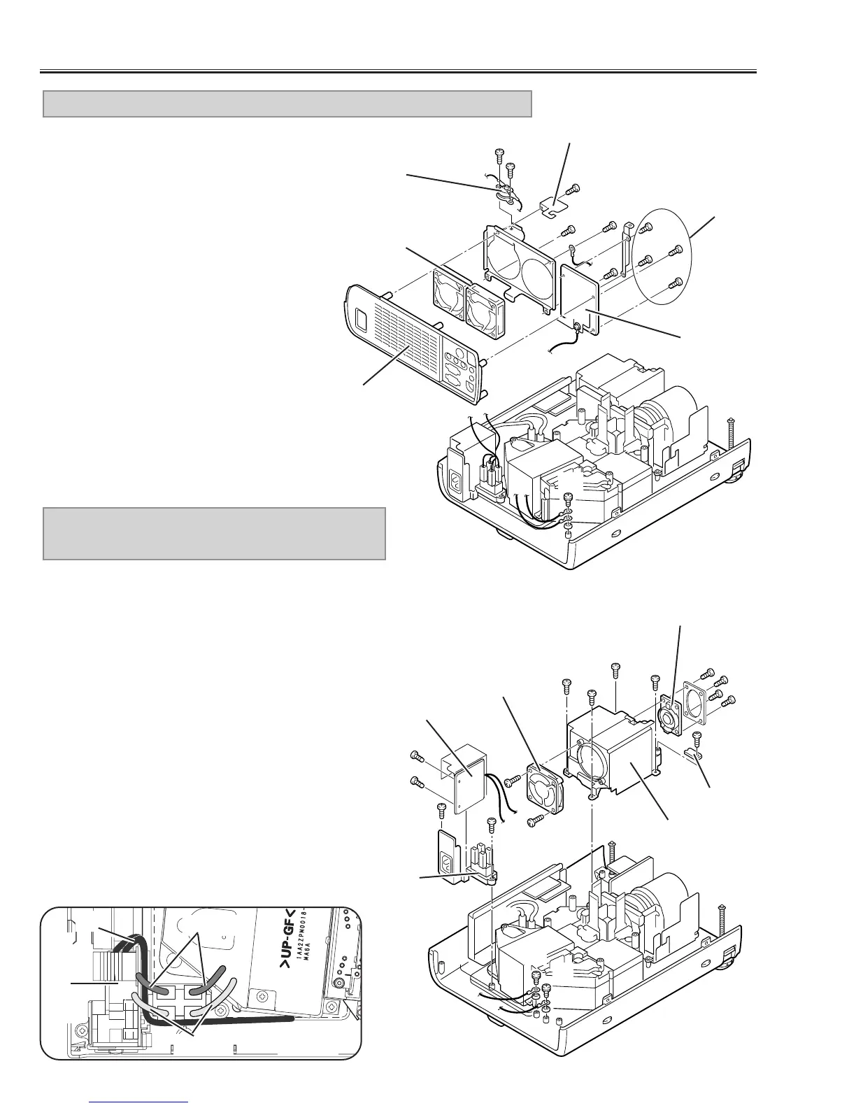
1) Pull the Rear Cabinet Ass’y upward.
2) Remove a screw (A) and take the
spacer off.
3) Remove 2 screws (B) and remove the
Thermal Switch (SW902).
4) Remove a screw (C) and remove the
grounding lead.
5) Remove 4 screws (D) and remove the
AV Board.
6) Remove 4 screws (E) and remove the
fans (FN904, FN905).
5. AV BOARD, REAR CABINET, FAN (FN904, FN905) REMOVAL
Fig.6
C
D
B
B
E
E
A
E
Rear Cabinet
Fan
(FN904, FN905)
Thermal Switch
(SW902)
Spacer
AV Board
1) Remove 4 screws (A) and remove the Power Cover.
2) Remove 2 screws (B) and remove the Fan (FN901).
3) Remove 4 screws (C) and remove the Speaker.
4) Remove a screw (D) and remove R/C Board.
5) Remove 2 screws (E) and remove the grounding
leads.
6) Remove 2 screws (F) and pull the Filter & Interlock
Switch Ass’y.
7) Remove 2 screws (G) and then remove the Filter
Board and the Interlock Switch Ass’y.
Note:
* When fixing the grounding lead of the Filter Board,
disconnect the lamp socket (refer to Fig.8) first, and
fix the grounding lead then connect the lamp socket.
* Dress the grounding lead (e), (f) as show in Fig.7-2.
* Make sure of wires color as shown in Fig.7-2 when
connecting the sockets.
6. POWER COVER, FAN (FN901), FILTER
BOARD REMOVAL