-26-
Electrical Adjustments
1. Receive the 16-step grey scale 480i-component signal
with Computer1 [Component] mode.
2. Enter the service mode.
3. Connect an oscilloscope to test point “TPG1” (+) and
chassis ground (-).
4. Select group no. “0”, item no. “0” and change data value
to adjust the pedestal level and black level to be the same
level.
5. Connect an oscilloscope to test point “TPR1” (+) and chas-
sis ground (-).
6. Select item no. “1” and change data value to adjust the
pedestal level and black level to be the same level.
7. Connect an oscilloscope to test point “TPB1” (+) and chas-
sis ground (-).
8. Select item no. “2” and change data value to adjust the
pedestal level and black level to be the same level.
Pedestal Lebel
Black Lebel
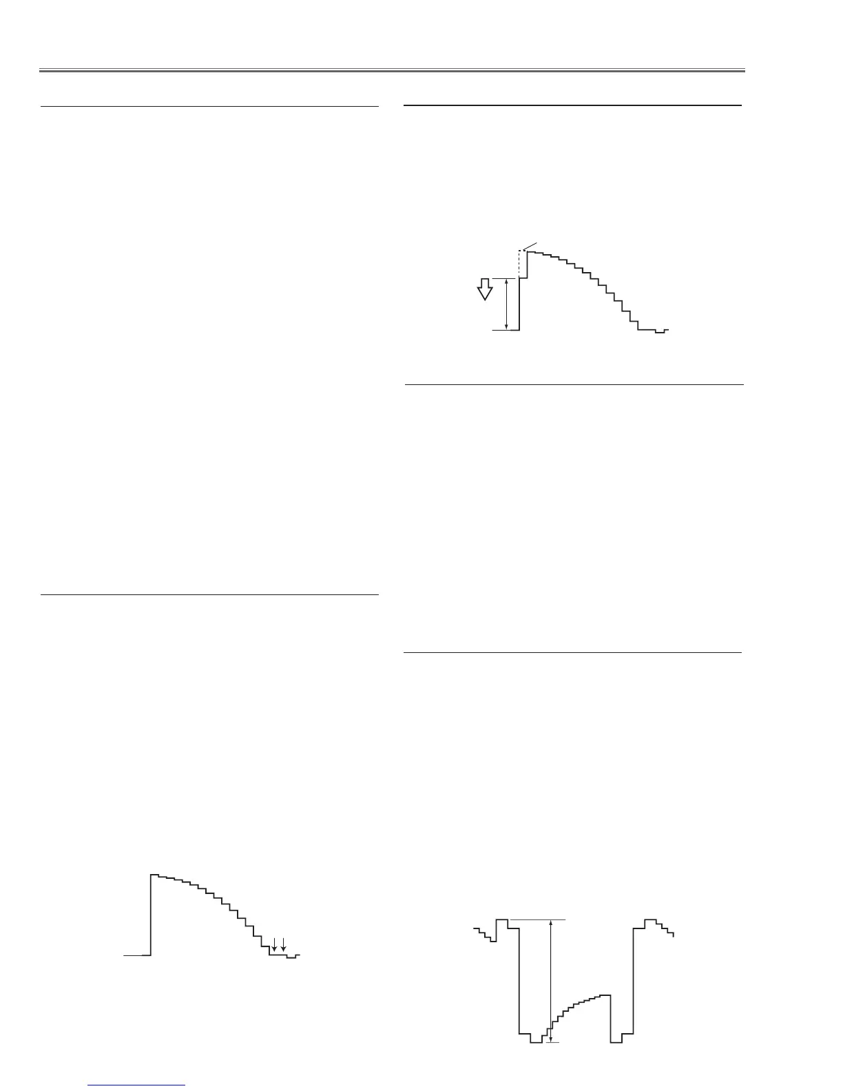
c Pedestal adjustment [480i]
1. Receive the 16-step grey scale 480i-component signal
with Computer1 [Component] mode.
2. Enter the service mode.
3. Connect an oscilloscope to test point “TPG1” (+) and
chassis ground (-).
4. Select group no. “0”, item no. “3” and adjust the amplitude
“a” to be minimum by changing the Data value.
v Gain adjustment [480i]
1. Receive the 16-step grey scale computer signal with Com-
puter1 [RGB]
mode.
2. Enter the service mode.
3. Connect an oscilloscope to test point “TPG1” (+) and chas-
sis ground (-).
4. Select group no. “100”, item no. “124” and change data
value to adjust amplitude “a” to be 10.0 ±0.1V.
5. Connect an oscilloscope to test point “TPR1” (+) and chas-
sis ground (-).
6. Select item no. “125” and change data value to adjust am-
plitude “a” to be 10.0 ±0.1V.
7. Connect an oscilloscope to test point “TPB1” (+) and chas-
sis ground (-).
8. Select item no. “126” and change data value to adjust am-
plitude “a” to be 10.0 ±0.1V.
(a)
black level
black level
n Black Reference adjustment
1. Enter the service mode.
2. Receive the 16-step grey scale computer signal with
Computer1 [RGB] mode.
3. To start the auto-calibration for PC adjustment, select
group no. “260”, item no. “0” and then change data value
from “0” to “1”. After the auto-calbration completed, "OK"
will appear on the screen.
4. Receive the 16-step grey scale composite video signal
with Video mode.
5. To start the auto-calibration for Video adjustment, select
group no. “260”, item no. “0” and then change data value
from “0” to “1”. After the auto-calbration completed, "OK"
will appear on the screen.
b Auto Calibration adjustment
1. Eenter the service mode.
2. Connect a digital voltmeter to test point “TPFANA” (+)
and chassis ground (-). Select group no. “250”, item no.
“95” and change data value to adjust voltage to be 13.5
±0.1V.
3. Connect a digital voltmeter to test point “TPFANB” (+)
and chassis ground (-). Select item no. “97” and change
data value to adjust voltage to be 13.5 ±0.1V.
4. Connect a digital voltmeter to test point “
TPFANA” (+)
and chassis ground (-). Select item no. “94” and change
data value to adjust voltage to be 5.0 ±0.1V.
5. Connect a digital voltmeter to test point “TPFANB” (+)
and chassis ground (-). Select item no. “96” and change
data value to adjust voltage to be 5.0 ±0.1V.
x Fan Control adjustment

 Loading...


