-32-
Electrical Adjustments
Gain adjustment [Component]
1. Enter the service mode.
2. Receive the 16-step grey scale 480i-component signal
with Computer1 [Component] mode.
3. Connect an oscilloscope to test point “TP35G” (+) and
chassis ground (-).
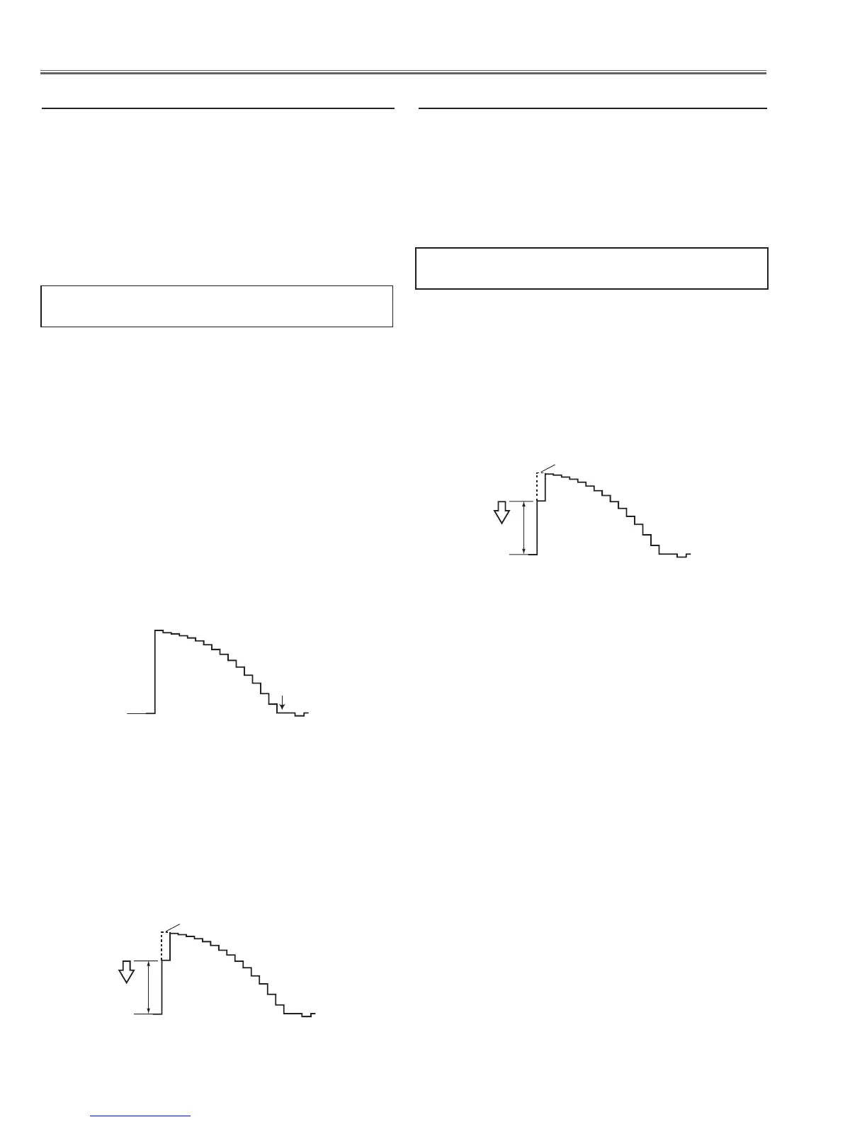
4. Select group no. “0”, item no. “3” and adjust the ampli-
tude “a” to be minimum by changing the Data value.
1. Enter the service mode.
2. Receive the 16-step grey scale composite video sig-
nal with Video mode.
3. To start the auto-calibration for Component adjust-
ment, select group no. “260”, item no. “0” and then
change data value from “0” to “1”. After the auto-cali-
bration completed, "OK" will appear on the screen.
Gain adjustment [Video]
1. Enter the service mode.
2. Receive the 16-step grey scale composite video signal
with Video [Video] mode.
3. Connect an oscilloscope to test point “TP35G” (+) and
chassis ground (-).
4. Select group no. “20”, item no. “0” and adjust the ampli-
tude “a” to be minimum by changing the Data value.
Below adjustment is performed when the above auto
calibration is failed.
4. Auto Calibration adjustment [Video]
1. Enter the service mode.
2. Receive the 8 color 100% color bar 480i-component
signal with Computer1 [Component] mode.
3. To start the auto-calibration for Component adjust-
ment, select group no. “260”, item no. “0” and then
change data value from “0” to “1”. After the auto-cali-
bration completed, "OK" will appear on the screen.
3. Auto Calibration adjustment [Component]
Below adjustments are performed when the above auto
calibration is failed.
Pedestal adjustment [Component]
1. Enter the service mode.
2. Receive the 16-step grey scale 480i-component signal
with Computer1 [Component] mode.
3. Connect an oscilloscope to test point “TP35G” (+) and
chassis ground (-).
4. Select Group No. “0”, Item No. “0” and change data
value to adjust the black level to be minimum.
5. Connect an oscilloscope to test point “TP35R” (+) and
chassis ground (-).
6. Select Item No. “1” and change data value to adjust the
black level to be minimum.
7. Connect an oscilloscope to test point “TP35B” (+) and
chassis ground (-).
8. Select Item No. “2” and change data value to adjust the
black level to be minimum.
 Loading...