-13-
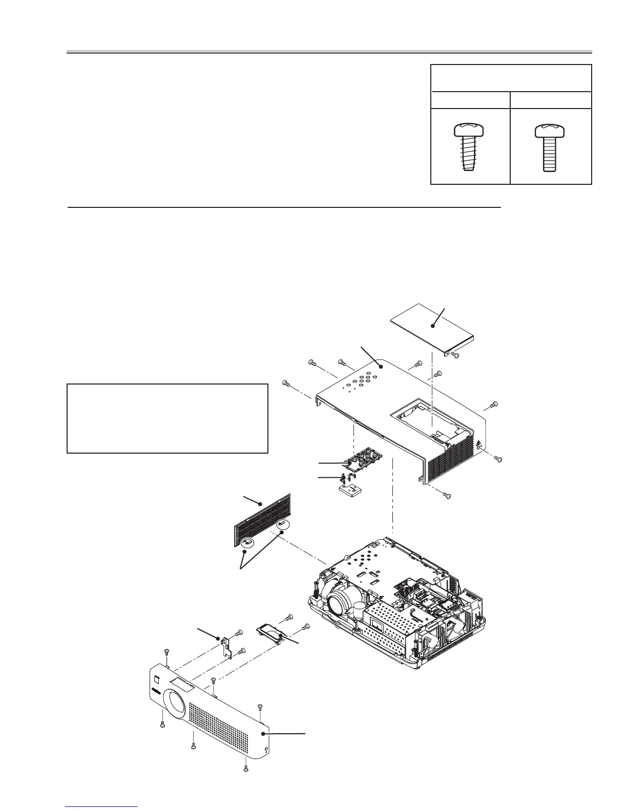
1. Filter cover (side), Cabinet Top, Front, RC Board removal
Mechanical Disassembly
Mechanical disassembly should be made following procedures in numerical or-
der.
Following steps show the basic procedures, therefore unnecessary step may
be ignored.
Caution:
The parts and screws should be placed exactly the same position as the original
otherwise it may cause loss of performance and product safety.
Screws Expression
(Type Diameter x Length) mm
T type M Type
B
RC Board
Fig.1
Cabinet top
1. Pull up two Latches to take off the Filter cover(side).
2. Loosen 1 screw-A to remove the Lamp Cover.
3. Remove 7 screws-B (M3x8) and 1 screw-C(M3x8) to remove the Cabinet Top.
4. Remove 3 screws-D (M3x8) and 3 screws-E (T3x8) to remove the Cabinet Front.
Control Buttons
Lamp Cover
A
B
B
D
D
D
F
Dec Inlay LED
Cabinet Front
G(T3x8)x2
G
Dec Lens
B
B
B
B
F(T3x8)x2
E
E
E
C
Filter cover(side)
Latches
Note on mounting the Cabinet top
When mounting the Cabinet top, mount
the Cabinet top first and then mount the
Lamp Cover, otherwise the Lamp Cover
switch(SW901) on the Fan holder may fail.
 Loading...