-31-
Electrical Adjustments
1. Enter the service mode.
2. Connect a digital voltmeter to test point “TPFANA” (+)
and chassis ground (-). Select group no. “250”, item
no. “0” and change data value to adjust voltage to be
4.0 ±0.1V.
3. Connect a digital voltmeter to test point “TPFANA” (+)
and chassis ground (-). Select item no. “1” and change
data value to adjust voltage to be 13.5 ±0.1V.
4. Connect a digital voltmeter to test point “TPFANB” (+)
and chassis ground (-). Select item no. “2” and change
data value to adjust voltage to be 5.2 ±0.1V.
5. Connect a digital voltmeter to test point “TPFANB” (+)
and chassis ground (-). Select item no. “3” and change
data value to adjust voltage to be 13.5 ±0.1V.
6. Connect a digital voltmeter to test point “TPFANC” (+)
and chassis ground (-). Select item no. “4” and change
data value to adjust voltage to be 3.5 ±0.1V.
7. Connect a digital voltmeter to test point “TPFANC” (+)
and chassis ground (-). Select item no. “5” and change
data value to adjust voltage to be 12 ±0.1V.
1. Fan Control adjustment
Gain adjustment [PC]
1. Enter the service mode.
2. Receive the 16-step grey scale computer signal with
Computer1 [RGB] mode.
3. Connect an oscilloscope to test point “TP35G” (+) and
chassis ground (-).
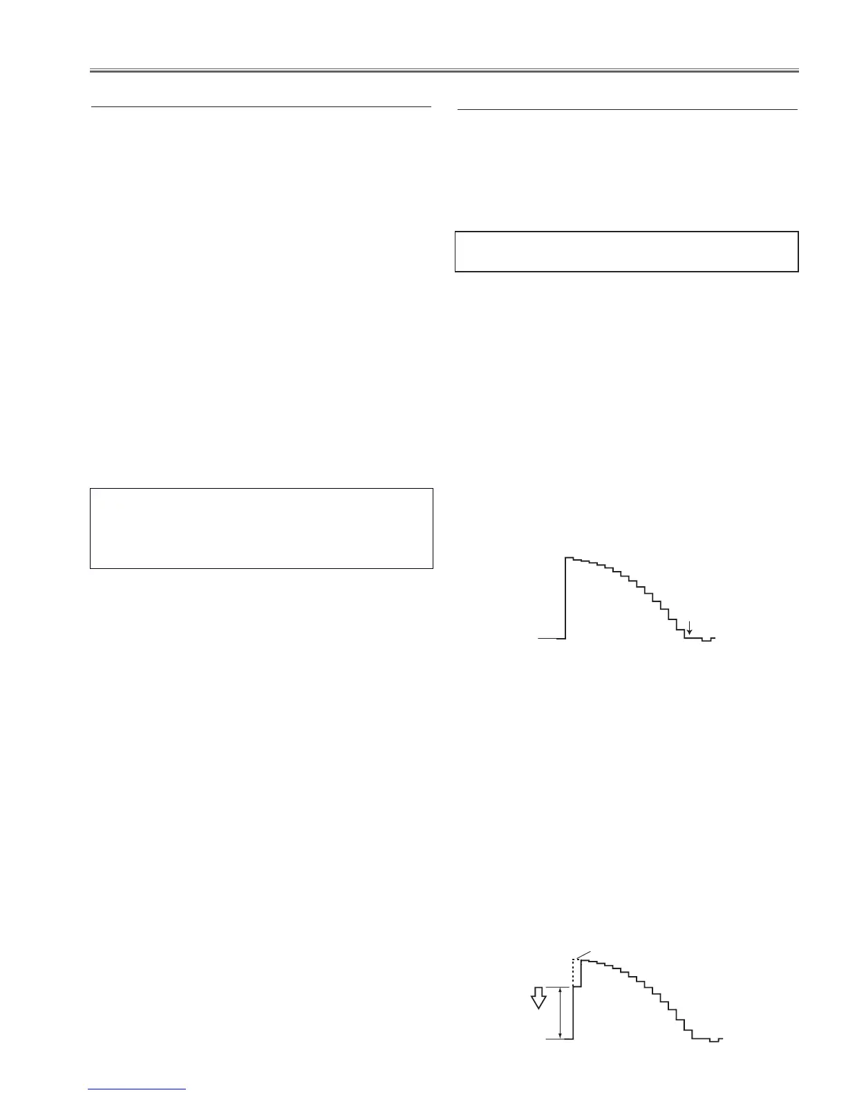
4. Select group no. “0”, item no. “3” and adjust the ampli-
tude “a” to be minimum by changing the Data value.
5. Connect an oscilloscope to test point “TP35R” (+) and
chassis ground (-).
6. Select group no. “0”, item no. “4” and adjust the ampli-
tude “a” to be minimum by changing the Data value.
7. Connect an oscilloscope to test point “TP35B” (+) and
chassis ground (-).
8. Select group no. “0”, item no. “5” and adjust the ampli-
tude “a” to be minimum by changing the Data value.
1. Enter the service mode.
2. Receive the 16-step grey scale computer signal with
Computer1 [RGB] mode.
3. To start the auto-calibration for PC adjustment, select
group no. “260”, item no. “0” and then change data
value from “0” to “1”. After the auto-calibration com-
pleted, "OK" will appear on the screen.
2. Auto Calibration adjustment [PC]
Below adjustments are performed when the above auto
calibration is failed.
Pedestal adjustment [PC]
1. Enter the service mode.
2. Receive the 16-step grey scale computer signal with
Computer1 [RGB] mode.
3. Connect an oscilloscope to test point “TP35G” (+) and
chassis ground (-).
4. Select Group No. “0”, Item No. “0” and change data
value to adjust the black level to be minimum.
5. Connect an oscilloscope to test point “TP35R” (+) and
chassis ground (-).
6. Select Item No. “1” and change data value to adjust the
black level to be minimum.
7. Connect an oscilloscope to test point “TP35B” (+) and
chassis ground (-).
8. Select Item No. “2” and change data value to adjust the
black level to be minimum.
Adjustments item no. [2] and [4] are carried out
at the spare parts shipment in the factory, there-
fore they are not required when the main board is
replaced with new one.
 Loading...