-60-
Troubleshooting
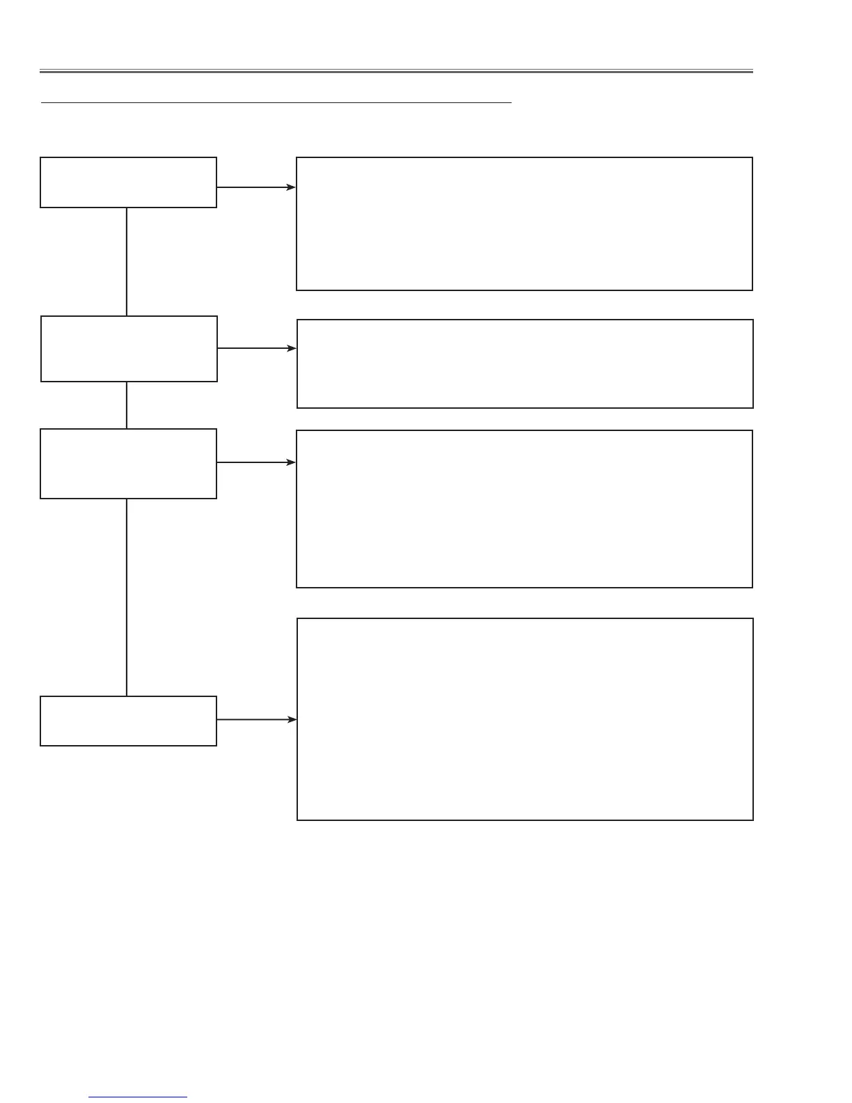
No Picture
Check following steps.
No picture with all of
input sources
Check signal processing stage and LCD driving stage;
Check RGB S&H signals at test points TP35B, TP35G, TP35R.
Check power supply circuit 15.5V_PNL and peripheral circuit.
Check ICs IC501, IC531, IC561, IC401, IC301 and peripheral circuits.
No picture with PC2
input source only
Check IC301<Scaler>, IC5301<HV Sync SW> and peripheral circuits.
R2, G2, B2 signals are applied at pins 172, 78, 256 of IC301.
HS2, VS2 signals are pins 253 and 66 of IC301.
MONIT_OUT signal is output from IC301 and applied to IC4701 and
IC4001.
Monitor-out selected; Pin 413 at IC301: H
Pins 1, 7 at IC4701: L
Pins 2, 4, 7 at IC4001: L
Yes
No
No
No
S-Video source
Check S-video signal (Y/C).
S_CHROMA signal is applied to pin 265 of IC301<Scaler>, and S-Y
signal is applied on pin 264 of IC301.
Composite video source
Check composite video signal (Video).
The composite video signal is applied to pins 262 of IC301 <Scaler>.
No picture with video
input sources
Yes
Check IC301<Scaler>, IC5301<HV Sync SW> and peripheral circuits.
R1, G1, B1 signals are applied at pins 82, 260, 258 of IC301.
HS1, VS1 signals are pins 331 and 161 of IC301.
No picture with PC1
input source only
Yes
Yes
 Loading...