Operating Design
Keys
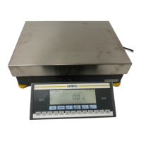
Your Factory scale is operated either
through the keys on the display and
control unit or via a connected PC.
Operation through the scale keys is
described in the following.
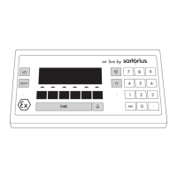
Function Keys (Soft Keys)
The current function of a soft key is
indicated in the bottom line of the display.
The bottom line shows symbols and/or
abbreviations to indicate soft key
functions. The abbreviations are usually
self-explanatory.
Example
isoTST: start calibration/adjustment
S ID: save ID
The function keys are numbered F1
through F6, from right to left.
The arrows shown in the footer indicate
the following functions:
oo Return to Setup menu
(in the Setup menu: save settings
and exit the Setup program)
o Go back to the higher selection level
O Show sub-items under the
active item
Q Move upward in the input/output
window
q Move downward in the input/output
window
l Set the selected menu parameter
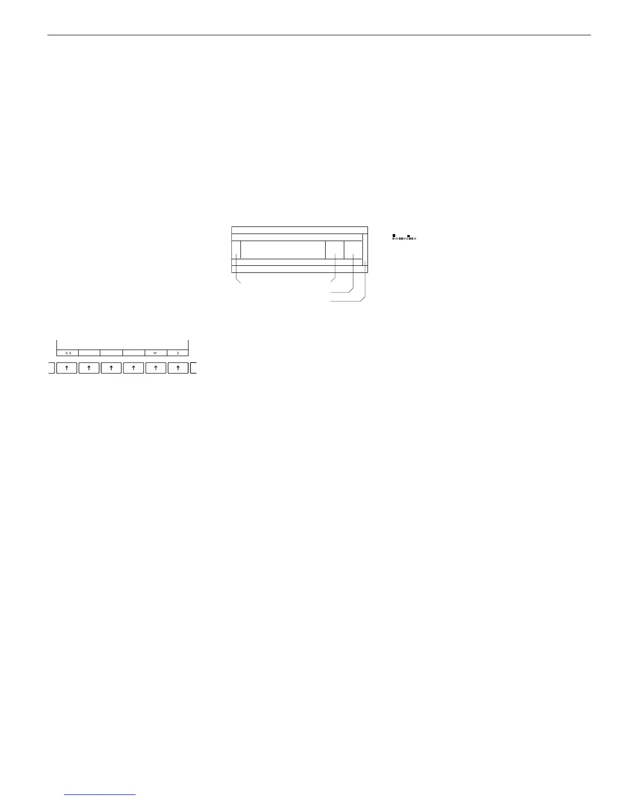
F6 F5 F4 F3 F2 F1
Display
There are two fundamentally different
types of display:
– display of measured and calculated
values
– display for menu parameter settings
(setup)
Display of Measured and
Calculated Values
This display is divided into nine sections.
Line for Metrological Data:
If the scale is verified for use in legal
metrology, the following metrological
specifications are shown here:
Max Maximum capacity of the scale
Min Minimum capacity of the scale;
i.e., the minimum weight
allowed when the scale is used
in legal metrology
e Verification scale interval
of the scale
d Readability: indicates the scale
interval of the scale
R1 Displayed when e = d
through
R4 e = d
On standard scales, only
Max and d
are shown.
Line for metrological data
Bar graph
Measured value line
Text line
Soft key labels
Plus/minus sign
Unit/Stability indicator
Tare memory
Calculated value
Application pictograms
Bar Graph:
The bar graph indicates how much of the
scale’s capacity is “used up” by the current
load; during checkweighing,
t indicates the control limits.
The following symbols may be
displayed here:
0% Lower load limit
100% Upper load limit
Bar graph showing 10% intervals
- Minimum for checkweighing
= Target for checkweighing
+ Maximum for checkweighing
Plus/Minus Sign, Stability Symbol:
A plus or minus sign (F or H) is shown
here for a weight value (e.g., a calculated
value when weighing in percent) or the S
symbol, indicating that the verified or
verifiable scale has been zeroed or tared.
Measured Value Line:
This section shows the weighed or
calculated value or alphanumeric input.
Note Concerning Verified Scales Approved
for Use as Legal Measuring Instruments
in the EU*:
For verified scales that have a verification
scale interval
e not equal to the scale
interval
d, the last digit on the display
is bordered
Unit and Stability:
When the scale reaches stability, the
weight unit or calculation unit is
displayed here.
The a symbol may be displayed for
readouts on a scale verified for legal
metrology. However, these readouts can
be used only for standard applications
(not in legal metrology/not legal for trade).
* including the Signatories of the Agree-
ment on the European Economic Area
4