EARTH TERMINAL (for grounding interferences)
If outside interference voltages act on the instrument, functional troubles may be
caused (concerns also high-frequency interferences). For grounding interferences
and ensuring the electromagnetic immunity, an earth must be connected: Terminal
22 must be connected to earth potential by means of a short cable (approx. 20 cm,
e.g. to cabinet ground)! Keep this cable separate from mains cables.
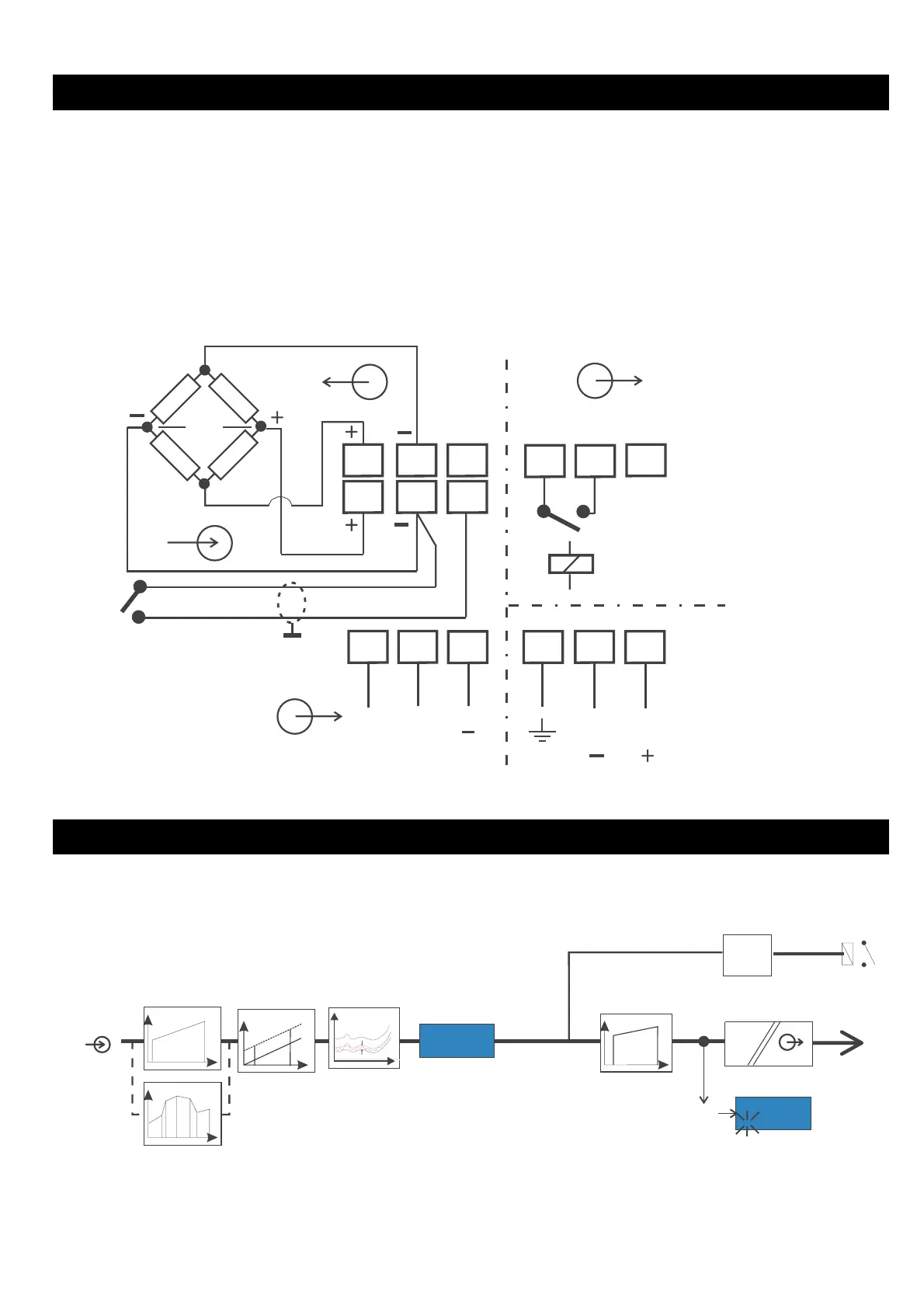
Connecting diagram: STRAIN GAUGE BRIDGE
Bridge supply
12VDC
(0,15A) relay output
max. 250VA; 230V
Input
SGB
[ mV]
supply voltage
U / I output (r hints Con2
)
SURVEY OF STRUCTURE
9408-800-25001 5
Con1
Con2
In 1
Ou 1
In 2
Ou 2
Con2
L_H
L_L
= x1xx
In 1.. . .
Ou1...
In n
Ou n
Con2
= x2xx
143.2
.10.2
OutL
OutH
t_F b_F
0/4...20mA
0/2 ... 10V
INPUT
M
U[mV]
%
0xx x
TARA
Figure 1: SURVEY OF STRUCTURE
21
2019
U+
U
I+
mV
mV
9
87
3
2
1
24
23
22
NL
12
11
10
max 250 VA; 230 V
0/4...20mA
0/2...10V
TARA / TARE
SGB
Relay
 Loading...