Do you have a question about the Sartorius PR 5210 Series and is the answer not in the manual?
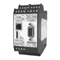
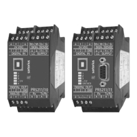
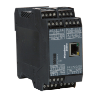
Details the three available models: PR 5210/00, PR 5210/10, and PR 5210/11.
Lists key technical specifications and features of the PR 5210 series.
Describes the wiring principle located on the housing's side.
Provides dimensions and design details of the transmitter housing.
Details load cell, RS 232, RS 485/422, analog output, opto inputs/outputs, and Profibus connections.
Outlines the intended use of the instrument and required operator qualifications.
Instructions for checking consignment for completeness and transport damage.
Covers installation, sensitive components, protective earth, and supply voltage.
Details procedures for repair, soldering, cleaning, and disposal.
Explains the function of the 5 green LEDs for operating and error status.
Describes the switch used to protect calibration data from unauthorized access.
Introduces setup and configuration via PC program or Profibus interface.
Guide on installing and launching the PC configuration software.
Procedures for loading, editing, and saving configuration data.
Describes how to print the current calibration data and parameters.
Explains how to select the user interface language in the software.
Details the information displayed on the status line of the configuration software.
Covers configuration of ADU parameters, including weighing point calibration and configuration.
Details the steps for calibrating the weighing point using different methods.
Configures parameters like overload, filter, frequency, and measuring time.
Details settings for analog output, Profibus, communication, limits, inputs, and outputs.
Configures analog output mode, range, error behavior, and values.
Specifies the address for the transmitter on the Profibus network.
Defines the bus size for data transfer, typically 8 bytes.
Configures serial line communication for remote displays or SMA protocol.
Sets the baudrate for serial communication, ensuring compatibility.
Sets or removes an access code for parameter protection.
Configures the behavior of the 3 digital outputs.
Configures the function of the 3 digital inputs.
Sets up to 3 pairs of limits for monitoring and generating signals.
Step-by-step guide for calibrating the weighing point using mV/V or weights.
Procedure for adapting the analog output current for receiver-side accuracy.
Explains how to view the actual status of weight, digital inputs, and outputs.
Overview of the SMA protocol for scale communication via RS485.
Defines symbols and characters used in the SMA protocol messages.
Lists and explains commands for requesting data and controlling the scale.
Details the format and meaning of scale responses to host commands.
Describes how the scale handles communication errors like parity or framing.
Explains the 8-byte read/write window protocol for Profibus communication.
Details the structure and usage of the Profibus write window for data transmission.
Details the structure and usage of the Profibus read window for data reception.
Procedures for reading and writing data via Profibus using specific windows.
Provides a detailed mapping of bits and bytes in the Profibus I/O area.
Explains how to read/write registers and control bits using Profibus.
Details the process for reading and writing parameters via Profibus.
Lists and describes various Profibus registers for status, data, and control.
Provides 10 status bits for dynamic status, read-only.
Contains dynamic scale status bits like Overload, Standstill, Errors.
Provides calibration information and error codes.
Stores actual gross, net, and tare weight values.
Allows reading and writing of parameter values and indices.
Stores and allows modification of limit setpoints.
Stores and allows modification of the analog output value.
Controls various transmitter functions via bits.
Explains how to access configuration and calibration data using parameter numbers.
Details parameters for analog output, communication, and digital I/O.
Guides the process of starting, performing, and saving calibration.
Describes ADU parameters like SetFullScale, Stepwidth, Deadload, Span.
Allows setting or retrieving the access code for parameter protection.
Technical details on the analog input and analog-to-digital conversion.
Specifications for the RS 232 serial interface.
Specifications for the RS 422/485 serial interface.
Technical specifications for the analog output.
Specifications for the digital inputs.
Specifications for the digital outputs.
Technical specifications related to the Profibus DP interface.
Details on the required power supply voltage and consumption.
Information on operating temperature, humidity, and EMC compatibility.
Physical dimensions, weight, and construction type.
Lists available accessories like software and cables.
Lists available options such as operation manuals.
Official declaration confirming compliance with European directives.
Certificate detailing type approval for the weighing instrument.
List of available spare parts with order numbers.
An example printout of the device's configuration and calibration data.
Provides the GSD file information for Profibus DP integration.
| Brand | Sartorius |
|---|---|
| Model | PR 5210 Series |
| Category | Transmitter |
| Language | English |