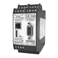
PR 5210 Operating Manual Technical Data
Sartorius 67
7 TECHNICAL DATA
The characteristic data are valid after a min. warm-up time of 30 minutes (reference temperature 23° C).
Values specified without tolerances are average values and are only used for information.
7.1 Analog part, A/D conversion
Principle DC voltage, Delta-Sigma conversion, ratiometric to the load cell supply
voltage
Measuring time Min. 10 ms to max 1920 ms)
Analog filter 1
st
order low-pass filter, cut-off frequency 70Hz
Digital filter Active 4
th
order (low-pass) Bessel, Aperiodic or Butterworth filter, cut-off
frequency adjustable (max. 0.25/measuring rate or approx.1.56 Hz)
7.1.1 Accuracy and stability
Accuracy class < 6000 d according to OIML R76 / EN 45501
Min. meas. signal (W&M) >
0.25 mV/V or > 3 mV for 6000 e
>
0.125 mV/V or > 1.5 mV for 3000 e
Linearity error < 0.002 %
Zero stability error TK
0
< 0.02 µV/K RTI
SPAN stability error TK
Spn
< +/- 2 ppm/K
7.1.2 Sensitivity
Sensitivity 0.5 µV/d @ 6000e according to OIML R76 / EN 45501
0.5 µV/d @ 3000e according to OIML R76 / EN 45501
0.2 µV/d, not for W&M
Resolution internal Approx 4.8 Mio steps for 36 mV
Min. meas. Signal >0.05 mV/V for 3000 d, not for W&M
Input voltage (meas.-signal + deadload) 0 ... max. 36 mV
Deadload range 36 mV - (max. meas. signal); entry/ calibration via software
7.1.3 Load cells
Load cell connection all strain gauge cells, 6 or 4-wire connection possible.
Load cell supply
U= ± 6 VDC for I
max
= 160 mA, protected by multifuses
Load cell supply circuit
12V DC for max. 8 load cells each with 650 Ω
for max. 4 load cells each with 350 Ω
Max. load
>
75 Ω

 Loading...