CONFIGURATION LEVEL
At configuration level, the unit is matched to the measuring task by means of an 8-digit
configuration code. The code is displayed in two 4-digit configuration words Con1 and
Con2 (symbol and value alternatively):
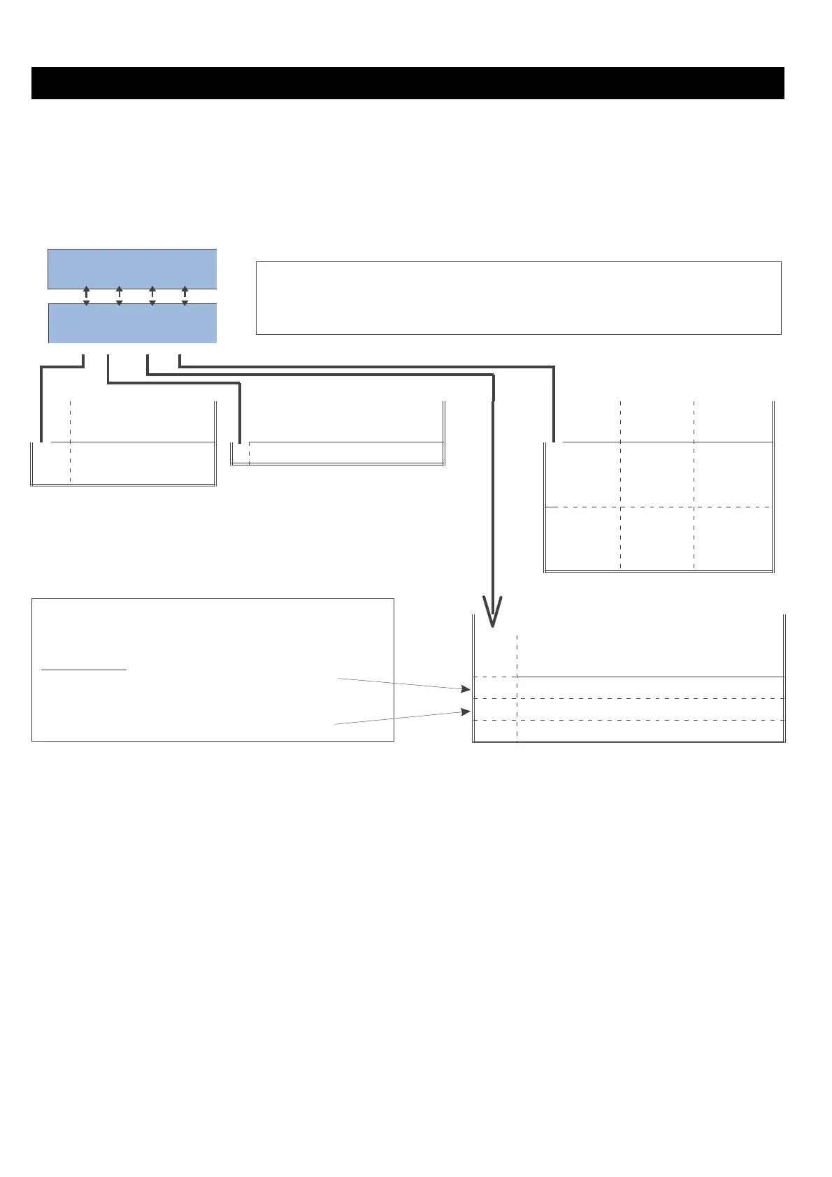
Structure of configuration word 1 ( Con1):
Pressing keys I and D changes the value of Con1 (the
longer the faster). When pressing M the change is effective
and Con2 will be displayed.
 Switching output
Input circuit
Sensor Meas.
Oper.
monitoring Sensor type
break
val.alarm principleÜ
0
upscale
5
Voltage
0
f
-
n.c.
1
downscale
1
-
f
n.c.
2
ff
n.c.
3
f
-
n.o.
4
-
f
n.o.
5
ff
n.o.
Input signal / measuring range with:
Voltage
[V]
0
-3...23mV
1
-11...69mV
2
0...160 mV
Ü Normally open operation: relay energized with alarm. Normally closed operation:relay de-energized with alarm.
g
Example for adjusting the configuration for Con1: 0500 :
0500 means: input circuit monitoring upscale/ Volt/ , range -3 ... 23mV / the
relay is de-energized with sensor break, no measurement value alarm!
+
When re-configuring the input type, all range-dependent parameters must be
matched to the new measuring range!
+
After re-configuring of input possibly delete input signal correction
(r page 15)!
8 9408-800-25001
1524
Con1
Supply voltage for load cells 12 V
Cell-Type:
1 mV/V generates max. 12mV
2 mV/V generates max. 24mV
 Loading...