Contents PR 5210 Operating Manual
4 Sartorius
4.8.2 Profibus Address................................................................................................................................................. 27
4.8.3 Bus size.................................................................................................................................................................. 28
4.8.4 Communication .................................................................................................................................................. 28
4.8.5 Baudrate................................................................................................................................................................ 28
4.8.6 Access..................................................................................................................................................................... 28
4.8.7 Outputs.................................................................................................................................................................. 28
4.8.8 Inputs..................................................................................................................................................................... 28
4.8.9 Limits...................................................................................................................................................................... 29
4.9 CALIBRATE ................................................................................................................................................. 30
4.10 ANALOG OUTPUT ADAPTION ...................................................................................................................... 31
4.11 STATUS....................................................................................................................................................... 32
4.11.1 Analog part weight status .............................................................................................................................. 32
5 SMA PROTOCOL ...........................................................................................................................33
5.1 GENERAL.................................................................................................................................................... 33
5.2 KEY TO SYMBOLS USED.............................................................................................................................. 33
5.3 SCALE COMMAND SET ............................................................................................................................... 34
5.3.1 Request Displayed Weight .............................................................................................................................. 34
5.3.2 Request High-Resolution Weight................................................................................................................. 34
5.3.3 Request Displayed Weight after Stability.................................................................................................. 34
5.3.4 Request Scale to Zero....................................................................................................................................... 34
5.3.5 Request Scale to Tare........................................................................................................................................ 35
5.3.6 Set Scale Tare Weight....................................................................................................................................... 35
5.3.7 Return Tare Weight........................................................................................................................................... 35
5.3.8 Clear Scale Tare Weight................................................................................................................................... 35
5.3.9 Invoke Scale Diagnostics ................................................................................................................................. 35
5.3.10 About Scale First Line....................................................................................................................................... 35
5.3.11 About Scale Scroll.............................................................................................................................................. 35
5.3.12 Scale Information .............................................................................................................................................. 36
5.3.13 Scale Information Scroll.................................................................................................................................. 36
5.3.14 Abort Command................................................................................................................................................. 36
5.3.15 Repeat Displayed Weight Continuously..................................................................................................... 36
5.4 SCALE RESPONSE MESSAGES ..................................................................................................................... 37
5.4.1 Standard Scale Response Message............................................................................................................... 37
5.4.2 Unrecognized Command Response.............................................................................................................. 38
5.4.3 Communication Error Response.................................................................................................................... 38
5.4.4 Diagnostics Command Response .................................................................................................................. 38
5.4.5 About ‘A’ and ‘B’ Command Response........................................................................................................ 38
5.4.6 Scale Information ‘I’ and ‘N’ Command Response..................................................................................39
5.5 COMMUNICATION ERROR HANDLING ......................................................................................................... 40
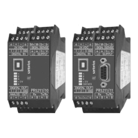
6 PROFIBUS INTERFACE.................................................................................................................41
6.1 PROFIBUS INTERFACE PROTOCOL................................................................................................................. 41
6.1.1 Write window (Input area) ............................................................................................................................. 42
6.1.2 Read window (Output area)........................................................................................................................... 42
6.1.3 Data reading and writing................................................................................................................................ 42
6.1.4 Description of I/O area (read/ write window) .......................................................................................... 43
6.1.5 Register read and write via Profibus........................................................................................................... 45
6.1.6 Parameter read and write via Profibus....................................................................................................... 48
6.2 PROFIBUS REGISTER ................................................................................................................................... 50
6.2.1 Register 0: IO-Status bits for reading......................................................................................................... 50
6.2.2 Register 1: Scale status.................................................................................................................................... 50
6.2.3 Register 2: Status of state controlled action bits................................................................................... 51
6.2.4 Register 3: Status of transition controlled action bits.......................................................................... 51
6.2.5 Register 4: Calibration information, error byte....................................................................................... 52
6.2.6 Register 5: Transmitter type and version................................................................................................... 53
6.2.7 Register 6: Board number ............................................................................................................................... 53
 Loading...