3
3
0
0
X
X
-
-
M
M
i
i
n
n
d
d
®
®
D
D
C
C
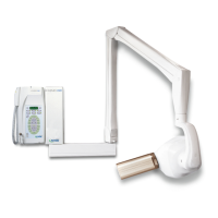
7. Withdraw the 26-pole connector from its seat to release both timer guards (Fig. 21)
Fig. 21
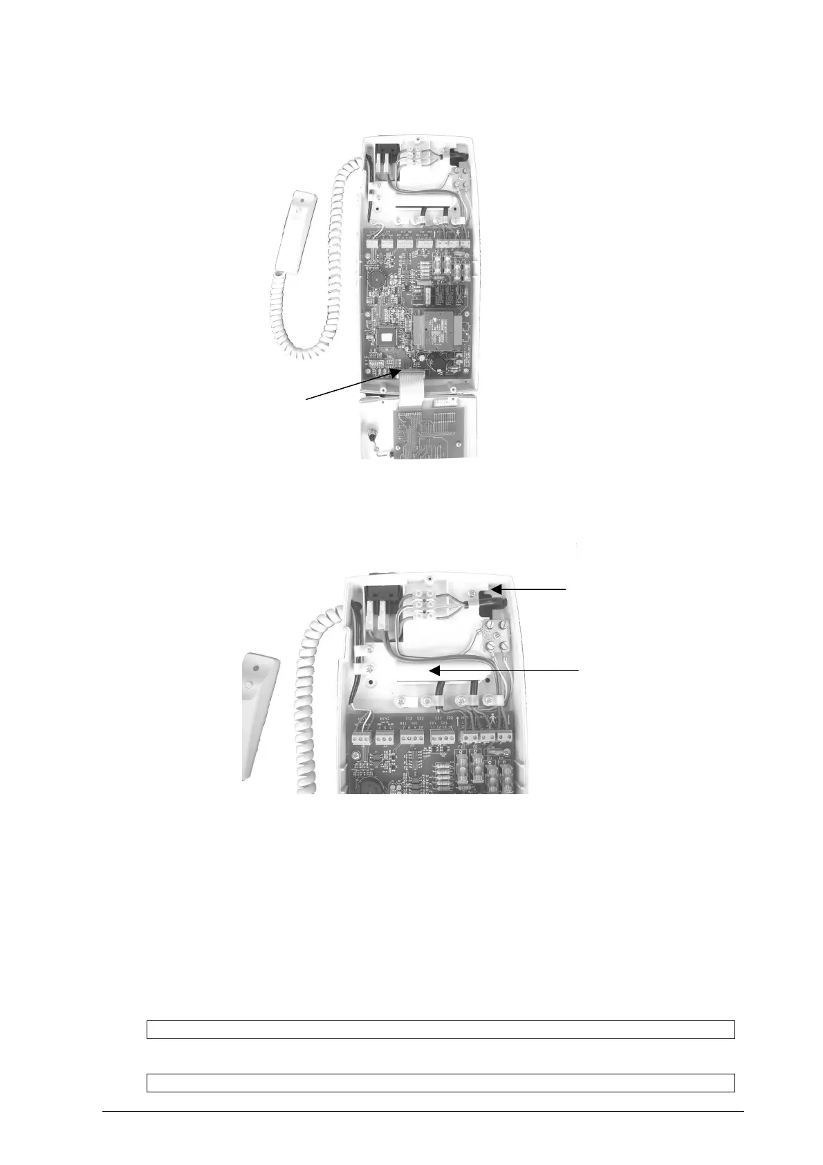
8. Insert the electrical feeding cables into the hole (Fig. 22)
Fig. 22
9. Insert the connection cables coming from the tubeheads into the rectangular slot
10. Insert the cables of the RX signaling lamp for external use (IF INSTALLED) (Fig. 22)
11. Insert the cables of the remote control button (IF INSTALLED) (Fig. 22)
12. Apply the timer base to the wall, matching the three anchor screws with the holes
13.
Insert and tighten the screws (refer to Fig. 20
) with the appropriate washers (refer to
Fig. 20
)
into the screw anchors
PLEASE NOTE
If the wall is uneven, insert some shims to prevent the timer from buckling.
PLEASE NOTE
Do not contaminate the timer with dust or rubble from drilling.
26-POLE CONNECTOR
FEEDING CABLE INLET HOLE
INLET HOLE FOR THE
TUBEHEAD(S)
RX SIGNALING LAMP(S) FOR
EXTERNAL USE CABLE
REMOTE CONTROL BUTTON(S)