X
X
-
-
M
M
i
i
n
n
d
d
®
®
D
D
C
C
3
3
5
5
The “ X-Mind
®
DC ” X-ray system is factory configured for “standard mode
” operation which
determines:
No. 2 “
X-Mind
®
DC ” tube heads
pressing the RX button
on the control
panel causes the LED 1 button to light up,
pressing the button again causes the LED 2 to
light up
** IF THE LONG 12” (31 cm) CONE IS USED **
An X-ray distance
SSD = 31cm
with the long 12” cone
on the control panel
LED 12” is lit
** IF THE SHORT 8” (20 cm) CONE IS USED **
An X-ray distance
SSD = 20cm
with the short 8” cone
on the control panel
8” LED is lit
with film type “D”
on the control panel
“D” LED is lit
no. 1 CONTROL BUTTON
to make the exposure
The timer includes a key with an extension
cable
The installed tube head has the following features:
work with
direct current at constant potential
the “DC” LED
on the control panel must be lit
work with
an X-ray voltage equal to 70kVp
the “70 kVp” LED
on the control panel must be lit
work with
an X-ray current equal to 8mA
the “8 mA” LED
on the control panel must be lit
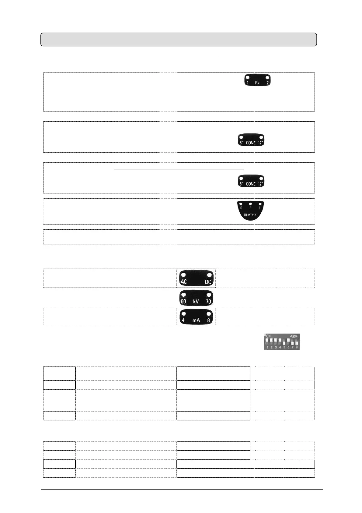
The above configuration depends on the position of 8 mini-switches (dip-switch
) on
the timer electronic card:
DIP
SWICH
PARAMETER ON OFF
1 TUBEHEAD No. 1 INSTALLED NOT INSTALLED
2 TYPE OF TUBEHEAD No. 1
dc
DIRECT CURRENT
AT CONSTANT POTENTIAL
ac
ALTERNATING CURRENT
SINGLE-PHASE
3 TUBEHEAD No. 2 INSTALLED NOT INSTALLED
4 TYPE OF TUBEHEAD No. 2
dc
DIRECT CURRENT
AT CONSTANT POTENTIAL
ac
ALTERNATING CURRENT
SINGLE-PHASE
5 CONTROL BUTTON No. 2 INSTALLED NOT INSTALLED
6 CONE LONG (12”) SHORT (8”)
7 NOT AVAILABLE NOT AVAILABLE
8 NOT AVAILABLE NOT AVAILABLE
7. SYSTEM CONFIGURATION