3
3
6
6
X
X
-
-
M
M
i
i
n
n
d
d
D
D
C
C
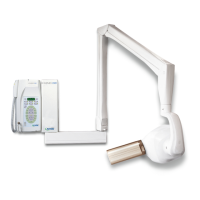
** IF THE LONG 12” (31 cm) CONE IS USED **
ON OFF
1
■
tubehead no. 1
2
■
“dc” type tubehead
3
■
tube head .no. 2
4
■
“dc” type tubehead
5
■
control button no. 2
6
■
12” cone (31cm)
7
■
not available
8
■
not available
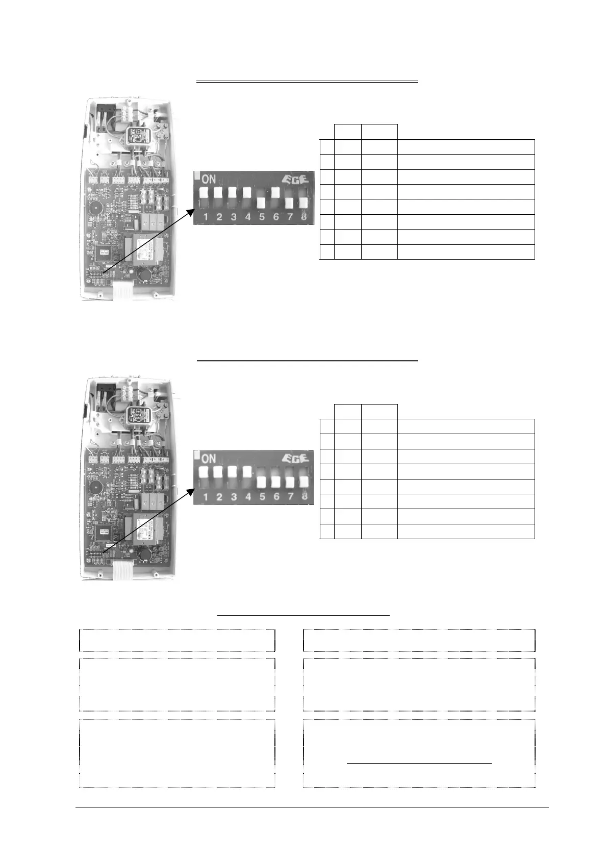
** IF THE SHORT 8” (20 cm) CONE IS USED **
ON OFF
1
■
no. 1tubehead
2
■
“dc type” tubehead
3
■
no. 2tubehead
4
■
“dc” type tubehead
5
■
no. 2 control button
6
■
8” cone (20 cm)
7
■
not available
8
■
not available
The configuration may be changed if:
POSSIBLE MODIFICATION
HOW TO CARRY OUT THE MODIFICATIONS
type “E” and “F” films are used
a digital system is used
use of a volta
e e
ual to 60 kV
use of a current e
ual to 4 mA
refer to USER’S MANUAL
§ 6 “OPERATING INSTRUCTIONS”
the short 8” (20 cm) cone is used
the long 12” (31 cm) cone is used
a single tubehead is used
use of a tubehead with “ac” technology
no. 2 CONTROL BUTTON is used
by changing the dip switch position
THIS ,MAY ONLY BE DONE BY THE INSTALLER