X
X
-
-
M
M
i
i
n
n
d
d
®
®
D
D
C
C
3
3
1
1
CAUTION
Before proceeding with connections, the power supply must be cut off.
CAUTION
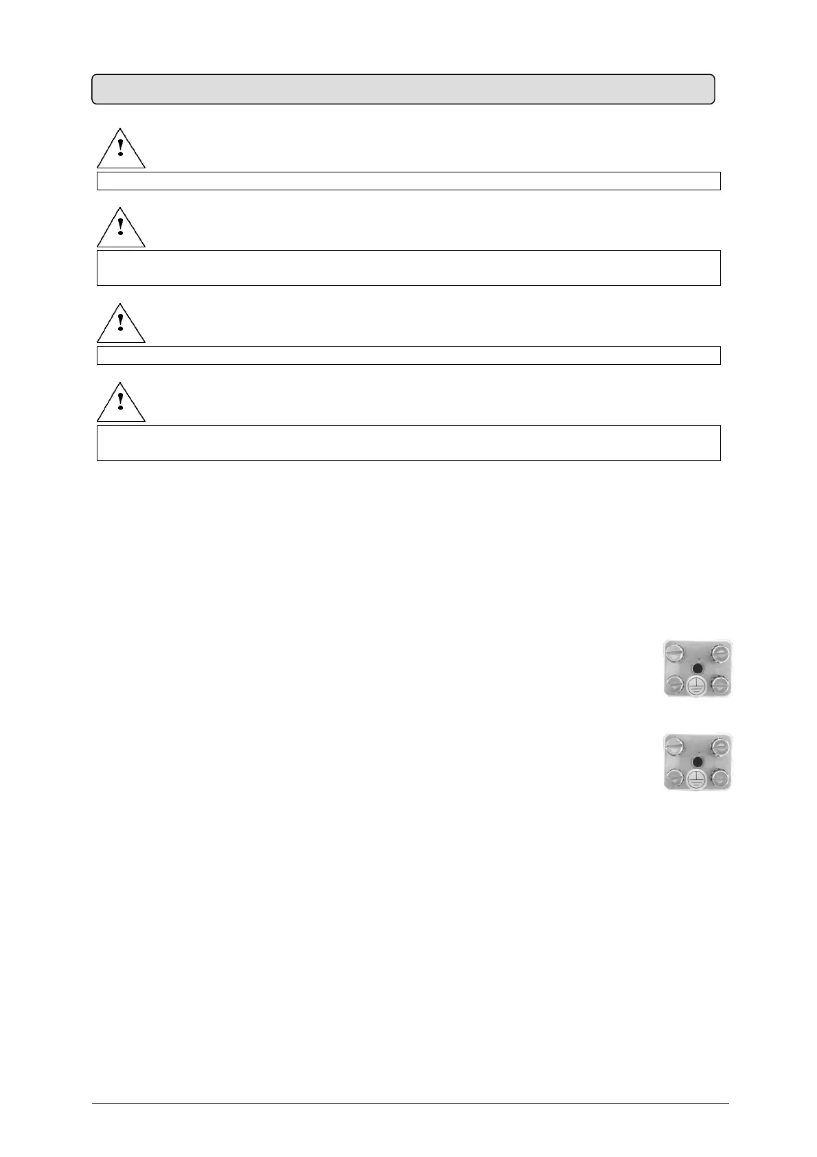
If the equipment is mounted on metal walls, these must be connected to the grounding
circuit.
WARNING
While performing the connection, always comply with the PHASE – NEUTRAL polarity.
WARNING
While stripping the cables, be careful that small copper wires do not fall on the printed circuit
and cause short circuits or malfunctioning.
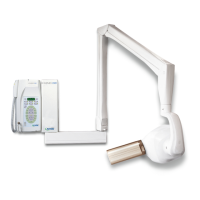
OPERATING INSTRUCTIONS (Fig. 23) (refer to §19 “ATTACHMENTS”)
1.
Connect the power supply cable to the terminal board
2. Insert the three mains cables into the rack
3.
Fix them with the cable clamp
4. Connect the cables coming from tubehead n° 1 to the terminals XRAY1
5.
Connect the YELLOW-GREEN grounding cable to the “equipotential metal plate”
6. Connect the cables coming from tubehead n° 2 to terminals XRAY2
7.
Connect the YELLOW-GREEN grounding cable to the “equipotential metal plate”
8.
Clamp the cables in the cable clamp
9. Connect the RX signaling lamps for external use (IF INSTALLED) (refer to §19 “ATTACHMENTS”)
10. Connect the remote control buttons (IF INSTALLED) (refer to §19 “ATTACHMENTS”)
11. Check the configuration on the dip switches (refer to §7 “SYSTEM CONFIGURATION”)
12. Reconnect the 26-pole connector
13. Close the timer with the three screws
14.
Mount the wall plate sliding cover and plug (refer to Fig. 6
)
15. Reconnect the power supply
5.9 TIMER ELECTRIC CONNECTION