RTC
®
4 PC Interface Board
Rev. 1.3 e
4 Principle Of Operation
33
innovators for industry
CO
2
Mode
The command
set_laser_mode(0)
selects the CO
2
laser mode. In this mode, the following laser signals
are available (see figure 16 on page 33):
• a LASERON signal
• two alternating modulation signals with variable
pulse width and frequency (LASER1 and LASER2)
The signals are available via the 9-pin D-SUB
laser connector – see page 52. The LASER1 and
LASER2 signals are additionally available at the LASER
EXTENSION connector.
The signals LASER1 and LASER2 have a constant
relative phase shift of 180° (half an output period).
LASER2 can be used for the control of a second laser
tube.
To control the laser power, the pulse widths of both
laser signals can be varied independently. However,
the output frequency of both signals is the same.
The output frequency and the pulse widths have to
be specified with the list command set_laser_timing
(see page 108). Please note that half of the output
period must be specified, i.e. the shift between the
two laser signals.
The command set_laser_timing is a list command,
i.e. it can be used anywhere in a list. This allows, for
instance, changing the laser power at any time within
a list.
Stand-By Mode
While the LASERON signal is inactive, the output
of signals LASER1 and LASER2 is reduced to stand-by
pulses. The pulse width and the output frequency of
these stand-by pulses are set with the command
set_standby (see page 116). They are equal for both
laser signals.
The stand-by pulses can be turned off by setting the
stand-by pulse width to zero (default setting).
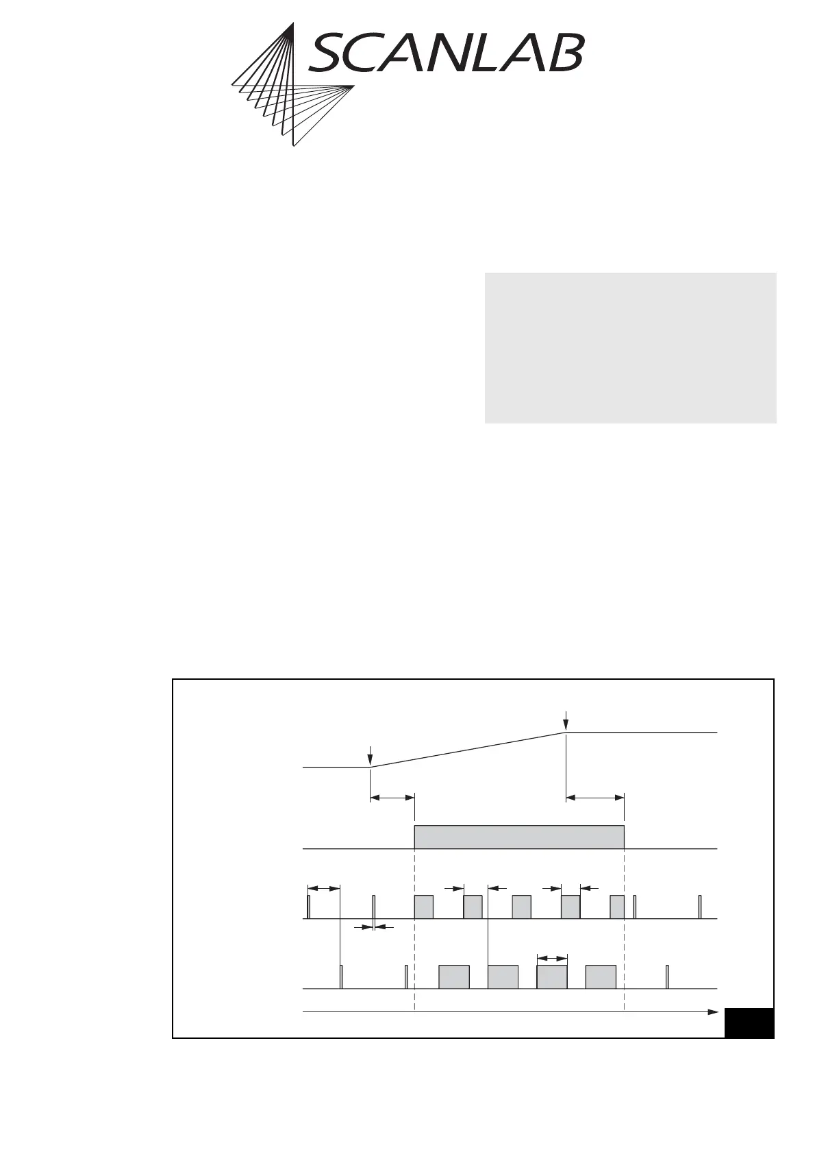
Time
LaserOff
Delay
LaserOn
Delay
LASERON
Vector
Output
Start of
Vector
End of
Vector
Laser2
Pulse Width
½ Stand-By
Period
Stand-By
Pulse Width
LASER1
LASER2
½ Output
Period
Laser1
Pulse Width
16
CO
2
Mode
Laser control timing diagram (CO
2
Mode)
• The actual output period and the pulse widths
of laser signals LASER1 and LASER2 depend on
the time base, which has to be specified with
the command set_laser_timing (see page 108).
The time base can be set to 1 MHz or 8 MHz.
In general, it is recommended to set the time base to
8MHz
(with
set_laser_timing(..,..,..,1)
).
A time base of 1 MHz should only be chosen if
necessary.