RTC
®
4 PC Interface Board
Rev. 1.3 e
8 Installation And Start-Up
59
innovators for industry
8.2 Changing The Jumper
Settings
TTL Laser Signal Level
The RTC
®
4 board permanently generates the
following laser signals (also see page 32 through
page 37):
•LASERON
• LASER1 / Q-Switch
• LASER2 / FirstPulseKiller
• Stand-By1, Stand-By2
All laser signals can be set to either active-low or
active-high logic via jumper X10:
Active-low means that a logical 1 ("Laser On", for instance)
is represented by a LOW level (0 V, TTL). Active-high means
a logical 1 is represented by a HIGH level (+5 V, TTL).
Set the jumper according to the specifications
of your laser control. Please refer to the
documentation of your laser.
Laser / Analog Output Ports
(9-Pin Laser Connector)
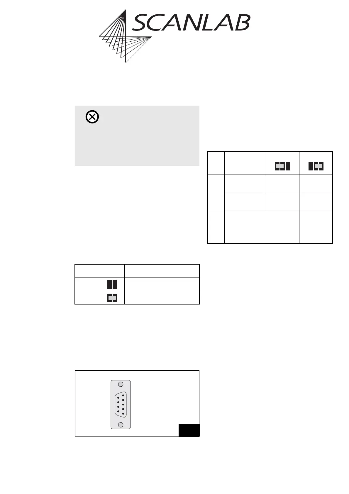
The signals at pins (2) and (4) of the 9-pin
laser output port connector (see figure 30 on
page 59) must be selected via jumpers X6, X7 and
X3. The following table summarizes the jumper
settings. For further information please refer to
section "How To Set The Jumpers", next.
How To Set The Jumpers
Jumpers X6 and X3
If you want to use the signal ANALOG OUT1
(e.g. for lamp current control), set the jumper
X6 to position 2-3. Then specify the output
voltage range with the Jumper X3 (see table).
Alternatively, the output signal at pin (4) can be
set permanently to +5 V (jumper X6 in position
1-2). In this case, jumper X3 can be ignored.
Jumper X7
If you need the TTL signal LASERON for laser
control, set the jumper X7 to position 1-2.
If your laser requires only the signals LASER1
and LASER2, you can use pin (2) for the signal
ANALOG OUT2 instead. To do this, set the
jumper X7 to position 2-3.
Note: The ANALOG OUT2 signal is also available
via the MARKING ON THE FLY connector.
(RTC
®
4 with Processing-on-the-fly option only)
For a description of the analog output signals please
refer to chapter "Analog Output ports", page 52.
Caution!
• The jumpers are soldered junctions. If you need
to change the jumper settings, you’ll have to
use a soldering-iron.
Please be careful not to damage the
electronics on the board!
Jumper X10 Laser Signal Logic
open active-low
closed active-high
30
(5) GND
(4) +5 V / ANALOG OUT1 *
(3) LASER2
(2) LASERON / ANALOG OUT2 *
(1) LASER1
/STOP (9)
/START (8)
GND2 (7)
GND2 (6)
Pin out of the 9-pin female D-SUB laser output port connector
* depends on jumper settings
Function Position 1-2 Position 2-3
X6 selects the
signal at pin (4)
+5 V
(max. 100 mA)
ANALOG
OUT1
X7 selects the
signal at pin (2)
LASERON ANALOG
OUT2
X3 sets the output
range of the
ANALOG OUT1
signal
0 … 2.56 V 0…10V
Jumper