RTC
®
4 PC Interface Board
Rev. 1.3 e
2 Product Overview
8
innovators for industry
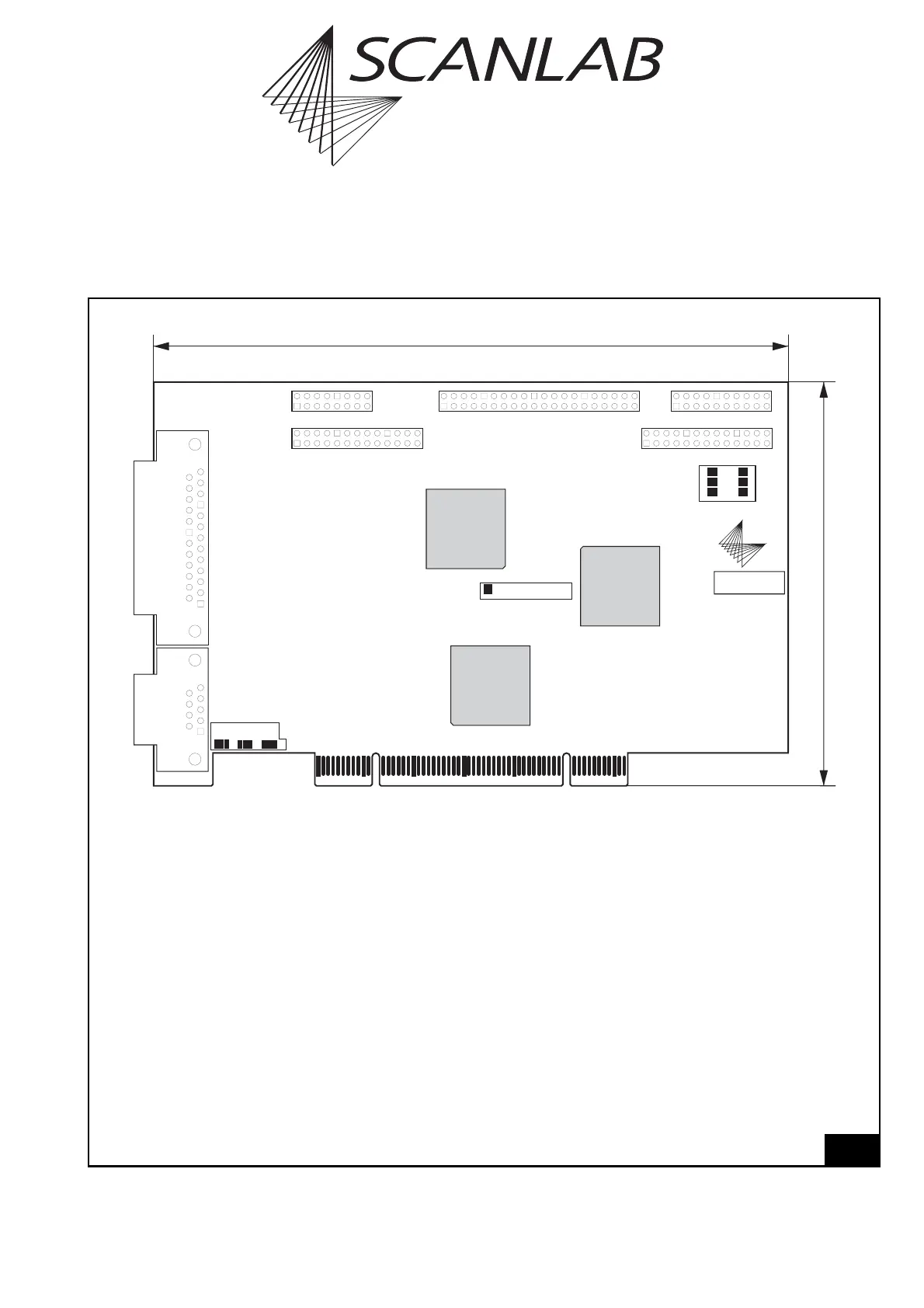
2.3 Board Dimensions And Layout
1
Legend
VB2 . . . . . . . . . . . . . . . . . . Primary scan head connector (D-SUB 25-pin female)
VB3 . . . . . . . . . . . . . . . . . . Laser connector and analog output ports (D-SUB 9-pin female)
MARKING ON THE FLY . . . . Connector for Processing-on-the-fly applications (optional) –
please refer to the supplement manual "Processing-On-The-Fly Software"
2. SCANHEAD . . . . . . . . . . Secondary scan head connector (optional)
EXTENSION 1. . . . . . . . . . . Connector with a 16-bit digital input and a 16-bit digital output
(optional: connector for the RTC
®
4 I/O Extension Board)
EXTENSION 2. . . . . . . . . . . Connectors for the RTC
®
4 I/O Extension Board (optional) –
please refer to the supplement manual "I/O Extension Board"
LASER EXTENSION . . . . . . . Additional laser connector with 8-bit digital output port
X6/X7/X3 . . . . . . . . . . . . . Jumper bank for laser connector VB3
X10 . . . . . . . . . . . . . . . . . . Jumper for setting the laser signal level
X8/X9 . . . . . . . . . . . . . . . . Jumper bank for the LASER EXTENSION connector
SN . . . . . . . . . . . . . . . . . . . Serial number
All connectors are described in section 6 on page 52.
The jumper settings are described in detail in section 8.1 on page 58.
VB3
VB2
X6 X7 X3
X10
X8 X9
SN
102 mm
160 mm
PCI CONNECTOR
MARKING ON THE FLY
2. SCANHEAD
EXTENSION 1 EXTENSION 2
LASER EXTENSION
Layout of the RTC
®
4 standard version