RTC
®
4 PC Interface Board
Rev. 1.3 e
8 Installation And Start-Up
60
innovators for industry
Digital Output Port
(Laser Extension Connector)
The 8-bit digital output port is available via the
LASER EXTENSION connector – see figure 24 on
page 53, odd numbered pins (1) to (17).
The port can be loaded with an 8-bit value
by the commands write_8bit_port and
write_8bit_port_list (see page 122).
The pins (15) and (17) of the output port have to be
configured via jumpers X8 and X9. The most signif-
icant bit (L7) of the 8-bit output value can be
assigned to pin (15) or to pin (17). Alternatively, each
of the two pins can be set permanently to +5 V
(HIGH) or to GND (LOW level).
Examples
• If the L7 bit is assigned to pin (15), the full 8-bit
output value is available on the output port
(odd numbered pins (1) to (15) of the
LASER EXTENSION connector).
• Setting pin (15) permanently to HIGH results in an
offset of 128 for the output value and restricts
the output values to (128 … 255).
• Setting pin (15) to LOW restricts the output value
to 0 … 127.
• The L7 bit can be used for other purposes by
assigning it to pin (17).
8.3 Installing the Hardware
Remove all diskettes and CDs from your PC.
Shut down the operating system and switch off
the PC. Disconnect the PC from the mains.
Remove the housing of the PC.
Locate a free PCI slot and remove the slot cover.
Remove the RTC
®
4 from the antistatic bag. Do
not touch the contacts of the board.
Install the RTC
®
4 into the PCI slot. Please observe
the instructions in the manual of your PC.
Close the housing of the PC.
Connect the 25-pin D-SUB connector to the scan
head via a data cable. Please refer to chapter 6.5
"Data Cable", page 55, for the specifications and
pinouts of the data cable.
Connect the 9-pin D-SUB connector on the RTC
®
4
to the laser via a suitable interface.
Check all connections and turn on the PC.
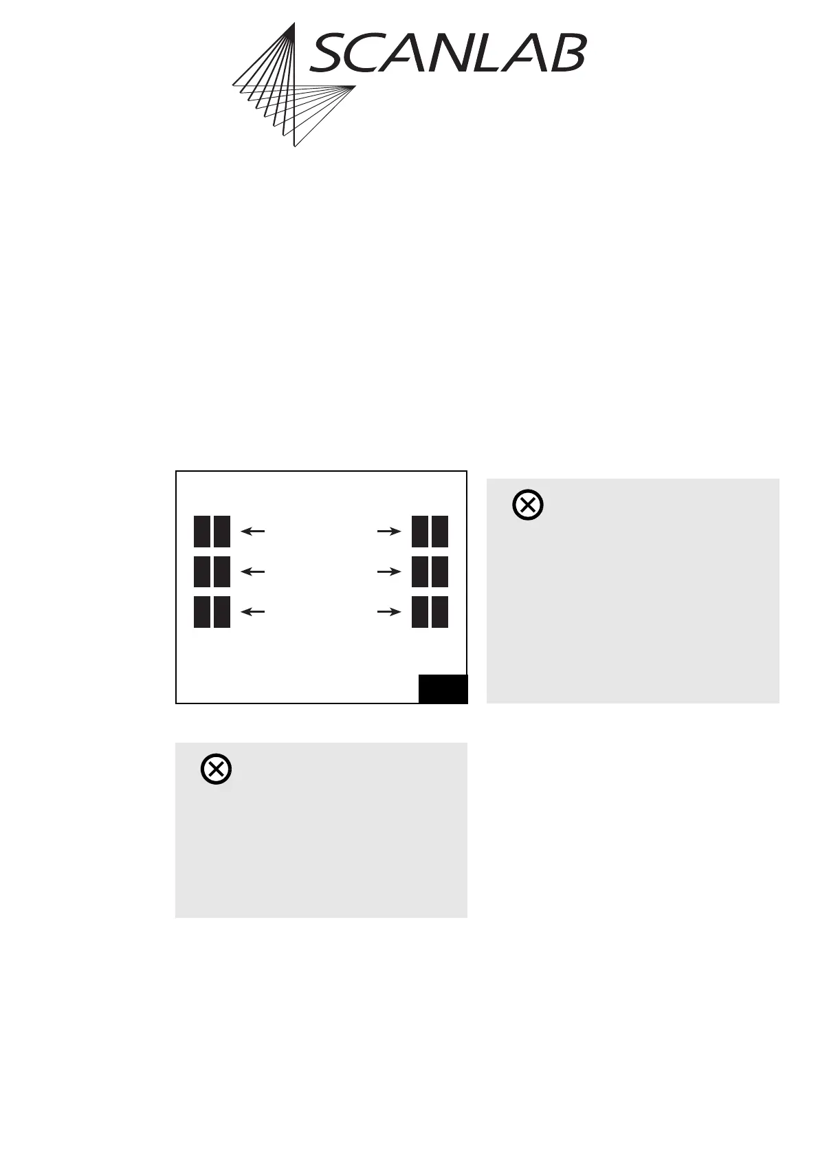
Caution!
• Make sure that not more than one of the three
jumpers at X8 is closed. Also make sure that not
more than one of the three jumpers at X9 is
closed.
Closing more than one jumper at positions
X8 or X9 will damage the electronics
on the board.
31
X8 X9
Close this jumper to set
Pin (15) / Pin (17)
to HIGH
Close this jumper to assign
the L7 bit to
Pin (15) / Pin (17)
Close this jumper to set
Pin (15) / Pin (17)
to LOW
Pin (15) Pin (17)
Caution!
• Please carry out the installation in an area that
complies with the Electro Static Discharge (ESD)
directives.
•RTC
®
4 and RTC
®
3 boards in the same computer
cannot be operated simultaneously.
• Do not touch the contacts of the RTC
®
4.
• Protect the board from humidity, dust, corrosive
vapors and mechanical stress.