RTC
®
4 PC Interface Board
Rev. 1.3 e
6 Electrical Connections
52
innovators for industry
6 Electrical Connections
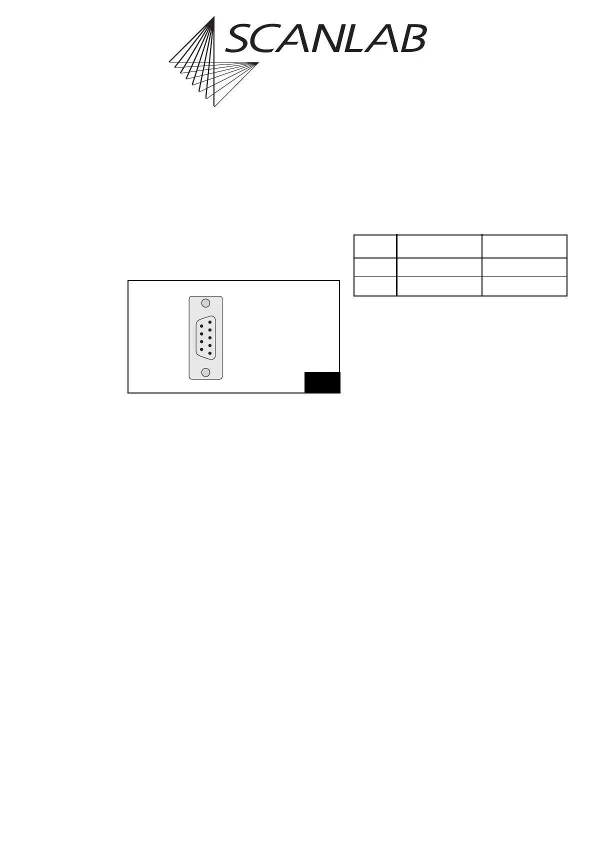
6.1 Laser Connector
Figure 23 shows the pin out of the 9-pin D-SUB
connector for the laser. The signals at pins (2) and (4)
are selected via jumpers. Please refer to the section
"Laser / Analog Output Ports (9-Pin Laser Connector)"
on page 59.
Analog Output ports
The RTC
®
4 provides two general purpose analog
output ports, ANALOG OUT1 and ANALOG OUT2.
They can be loaded directly or via a list with the
commands write_da_x / write_da_x_list (see
page 123), respectively. The output resolution of
both ports is 10 bits.
The output voltage range of the ANALOG OUT1 port
can be set to either 0 V … 2.56 V or 0 V … 10 V.
The range of the ANALOG OUT2 port is fixed at
0V…10V.
Both signals are referenced to PC ground (GND). The
maximum current load of both signals is 5 mA.
If jumper X6 has been configured to replace the
ANALOG OUT 1 signal with +5 V, then the maximum
current load at pin (4) of the laser connector is 100
mA.
Further input and output ports are provided by the
optional RTC
®
4 I/O Extension Board from SCANLAB
(see "Options", page 57).
Laser Signals
The output signals LASER1 and LASER2 depend on
the selected laser control mode:
Please refer to the laser timing diagrams on
page 33 (CO
2
Mode) and page 36 (YAG Modes).
All laser outputs (LASERON, LASER1 and LASER2) are
digital TTL level signals (alternatively active-high or
active-low, see page 59) and are referenced to GND2.
The maximum current load is 10 mA.
If the RTC
®
4 is supplied with optoelectronic couplers,
GND and GND2 are optically decoupled. Otherwise
GND and GND2 are identical. See chapter 7 "Options",
page 57.
External Control Signals
The external control signals /START and /STOP
(TTL active-low) are referenced to GND. Both input
signals are connected internally to +5 V via pull-up
resistors. Please refer to the section "External Control
Inputs", page 13.
23
(5) GND
(4) +5 V / ANALOG OUT1 *
(3) LASER2
(2) LASERON / ANALOG OUT2 *
(1) LASER1
/STOP (9)
/START (8)
GND2 (7)
GND2 (6)
Pin out of the 9-pin female D-SUB connector for the laser (VB3)
* depends on jumper settings
CO
2
Mode YAG Modes 1 / 2
LASER1 Modulation pulse 1 Q-Switch signal
LASER2 Modulation pulse 2 FirstPulseKiller