RTC
®
4 PC Interface Board
Rev. 1.3 e
4 Principle Of Operation
37
innovators for industry
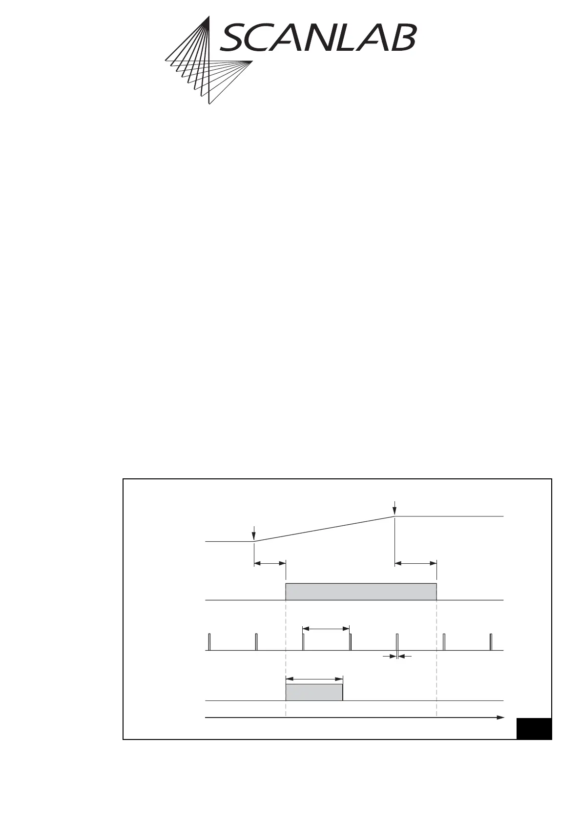
Laser Mode 4
The command
set_laser_mode(4)
selects the laser
mode 4. In this mode, the following laser signals are
available (see figure 18 on page 37):
• a LASERON signal
• a continuously-running modulation signal with
variable pulse width and frequency (LASER1). The
signal is provided for an active LASERON signal as
well as for an inactive LASERON signal (as standby
signal).
• a programmable FirstPulseKiller signal (LASER2)
The signals are available via the 9-pin D-SUB
laser connector – see page 52. The LASER1 and
LASER2 signals are additionally available at the LASER
EXTENSION connector.
The pulse width and the output period of the LASER1
modulation signal are set with the command
set_standby (see page 116) or set_standby_list (see
page 116). In the default setting the pulse width is
set to zero. Please note that half of the output period
must be specified. The maximum allowed pulse width
is the half stand-by period.
The FirstPulseKiller signal is started together with the
LASERON signal. The length of the FirstPulseKiller
signal is set with the command set_firstpulse_killer
or set_firstpulse_killer_list (see page 105).
In laser mode 4 the time base for the signals LASER1
and LASER2 is always 1/8 µs.
Time
LaserOff
Delay
LaserOn
Delay
LASERON
Vector
Output
Start of
Vector
End of
Vector
LASER1
Stand-By
Period
FirstPulseKiller
Length
LASER2
(FirstPulseKiller)
Stand-By
Pulse Width
18
laser mode 4
Laser control timing diagram (laser mode 4)