RTC
®
4 PC Interface Board
Rev. 1.3 e
8 Installation And Start-Up
58
innovators for industry
8 Installation And Start-Up
Installation of the RTC
®
4 consists of the following
steps:
(1) configuring the RTC
®
4 jumpers
(2) installing the RTC
®
4
(3) installing the RTC
®
4 software drivers
Please proceed in the order described in the following
sections.
8.1 Jumper Settings Overview
The factory settings for the RTC
®
4 jumpers are listed
on the supplement at the end of this manual.
If you do not want to change the factory settings,
proceed with chapter 8.4 "Installing the Drivers",
page 61.
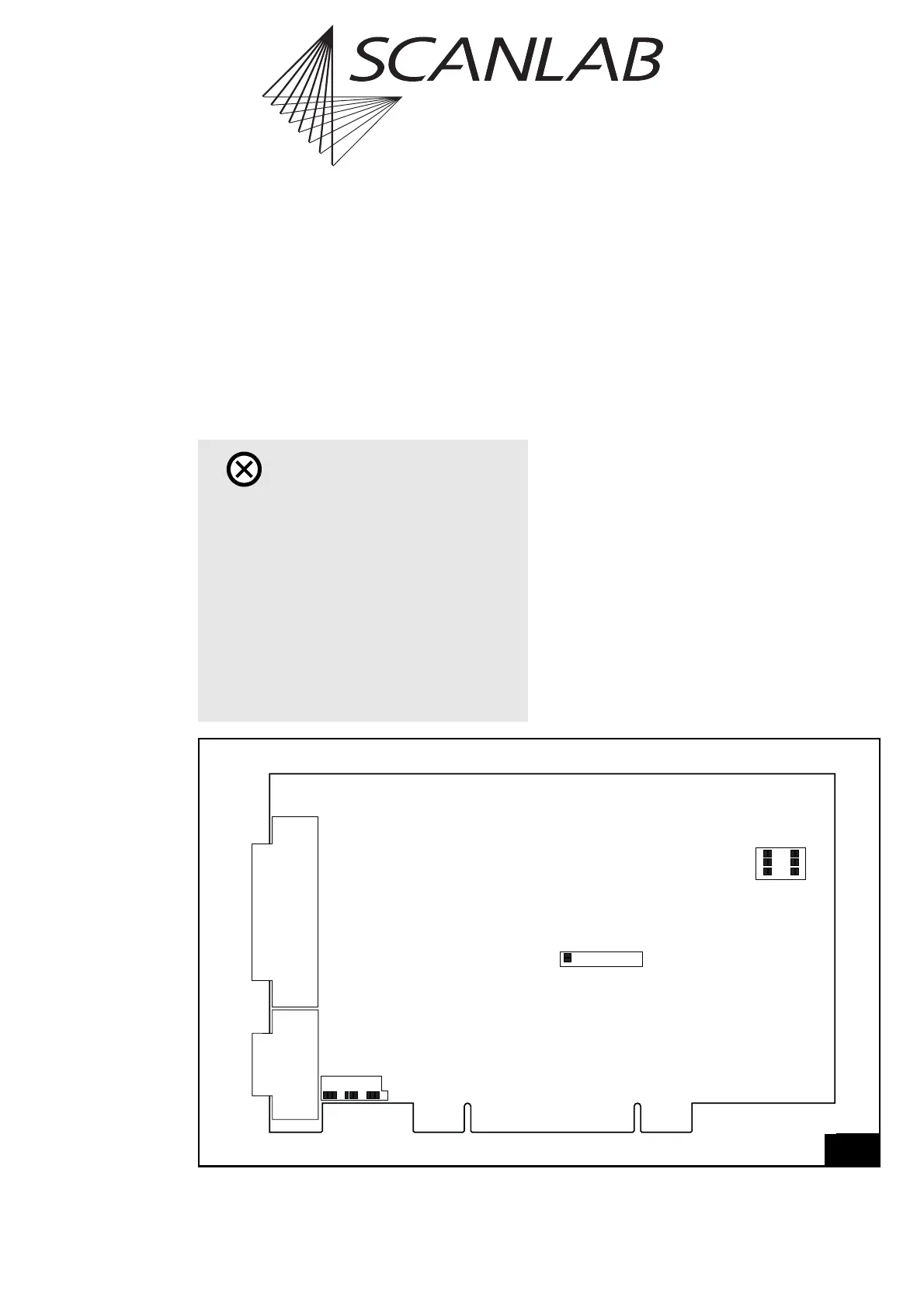
The following jumpers can be set by the user (see
figure 29 on page 58):
• Jumper for the laser signals (X10)
(active-high or active-low)
• Jumpers for the 9-pin D-SUB laser connector
(X6, X7, X3)
• Jumpers for the 8-bit digital output port on the
LASER EXTENSION connector (X8, X9) (optional)
Caution!
•RTC
®
4 boards cannot be used simultaneously
with RTC
®
3 boards in the same PC.
• Prior to installing software drivers for
WINDOWS XP and WINDOWS 2000, previously
installed drivers of the old, discontinued version
must be de-installed.
• For installing the old, discontinued driver
version for WINDOWS XP SP1 / 2000 / NT 4 and
WINDOWS ME / 98 / 95 the software drivers
must be installed before the RTC
®
4 board is
installed into the PC.
29
X6 X7 X3
X10
X8 X9
Jumper positions on the RTC
®
4 board