RTC
®
4 PC Interface Board
Rev. 1.3 e
4 Principle Of Operation
24
innovators for industry
Notes On Optimizing The Delays
The delays have to be set with the commands
set_scanner_delays and set_laser_delays. The
delays have to be appropriate for the defined jump
speed and the marking speed. If the delays are not
optimized, the quality of the scanning results will be
reduced and scanning time will be extended.
The figures on page 26 through page 28 show the
various effects of non-optimized delays on the letters
"RTC".
The lengths of the LaserOn delay and the LaserOff
delay have no influence on the total scanning time if
positive values are chosen.
The LaserOn delay and the LaserOff delay should be
optimized first, followed by the delays for scanner
control, i.e. the jump delay, the mark delay and the
polygon delay.
When optimizing the laser delays, it is useful to set
the jump delay and the mark delay to long values.
Limits For The Delays
When setting the delays, please observe the
following:
The reasons for the two constraints (1) and (2)
can be understood as follows:
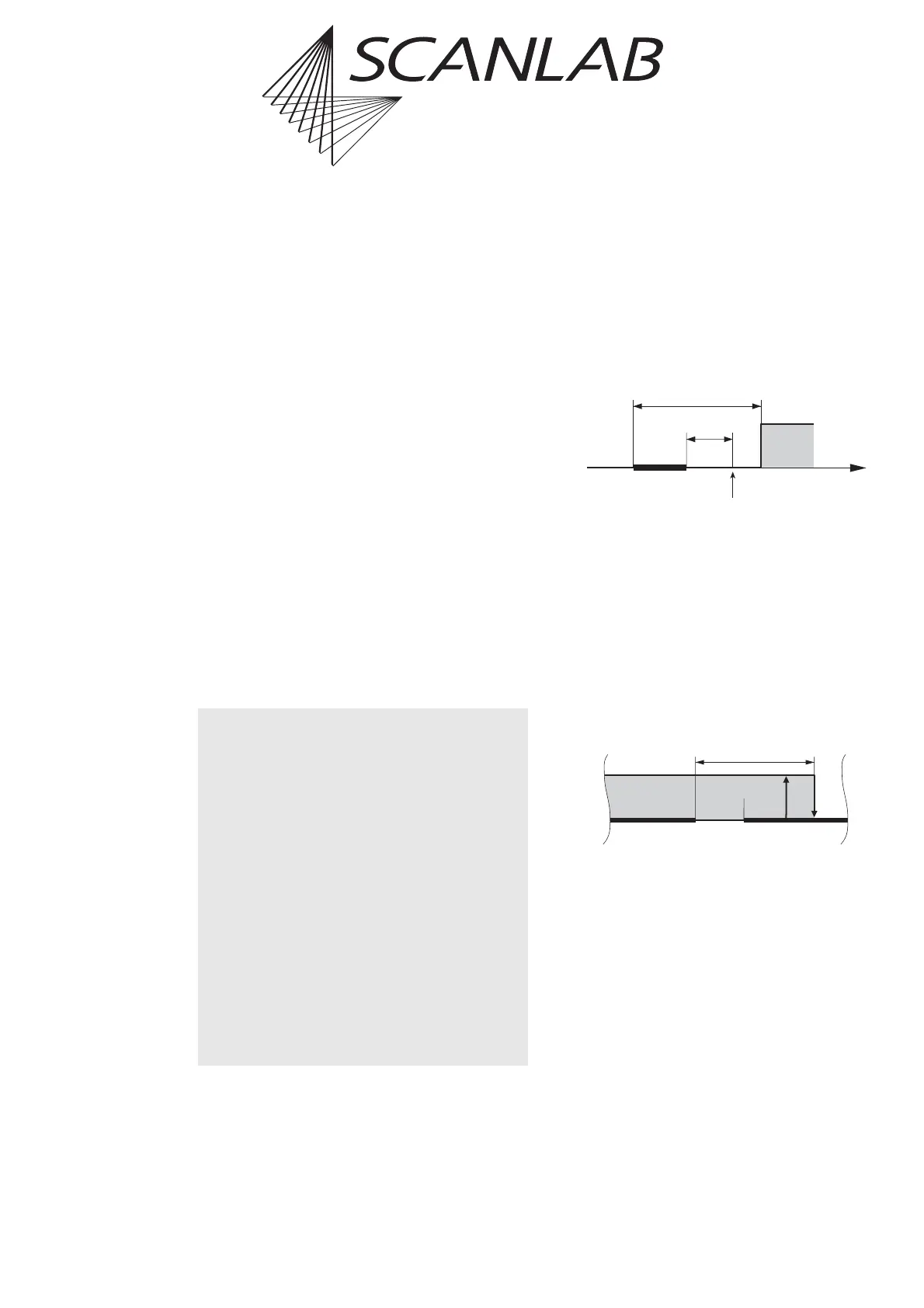
(1) Consider a very short mark command.
If the sum of the marking time and the LaserOff delay is
shorter than the LaserOn delay, the LaserOff delay will
be over before the LaserOn delay has finished.
Thus the RTC
®
4 will first try to turn the laser off and
afterwards turn it on:
This can be avoided by always setting the LaserOff delay
longer than the LaserOn delay.
LOffD > LOnD [1]
(2) Consider two subsequent mark commands.
If the LaserOff delay (after the first mark command) is
longer than the sum of the mark delay and the LaserOn
delay (for the second mark command), the RTC
®
4 will
turn off the laser during the second mark command:
To avoid this, the sum of the mark delay and the
LaserOn delay must be longer than the LaserOff delay.
markD + LOnD > LOffD [2]
In practice, the laser delays are usually optimized first.
When the laser delays are fixed, equation [2] reads:
markD > LOffD – LOnD [3]
i.e. the mark delay must be longer than the difference
between the LaserOff delay and the LaserOn delay.
(1) The LaserOff delay must be longer than the
LaserOn delay. Otherwise faults in the laser
control may occur.
LOffD > LOnD
(2) The mark delay must be longer than the
difference between the LaserOff delay and
the LaserOn delay.
markD > LOffD – LOnD
The same applies to the edgelevel of the variable
polygon delay:
edgelevel > LOffD – LOnD
Please note that the laser delays must be speci-
fied in units of 1 µs, whereas the scanner delays
(jump delay, mark delay and polygon delay)
must be specified in units of 10 µs.
Time
Short Mark
Command
Laser
LOff D
LOn Delay
RTC3 tries to
turn the laser off
1
st
Mark
Command
LOn
Delay
LOff Delay
2
nd
Mark
Command
Mark
Delay
Laser