RTC
®
4 PC Interface Board
Rev. 1.3 e
6 Electrical Connections
53
innovators for industry
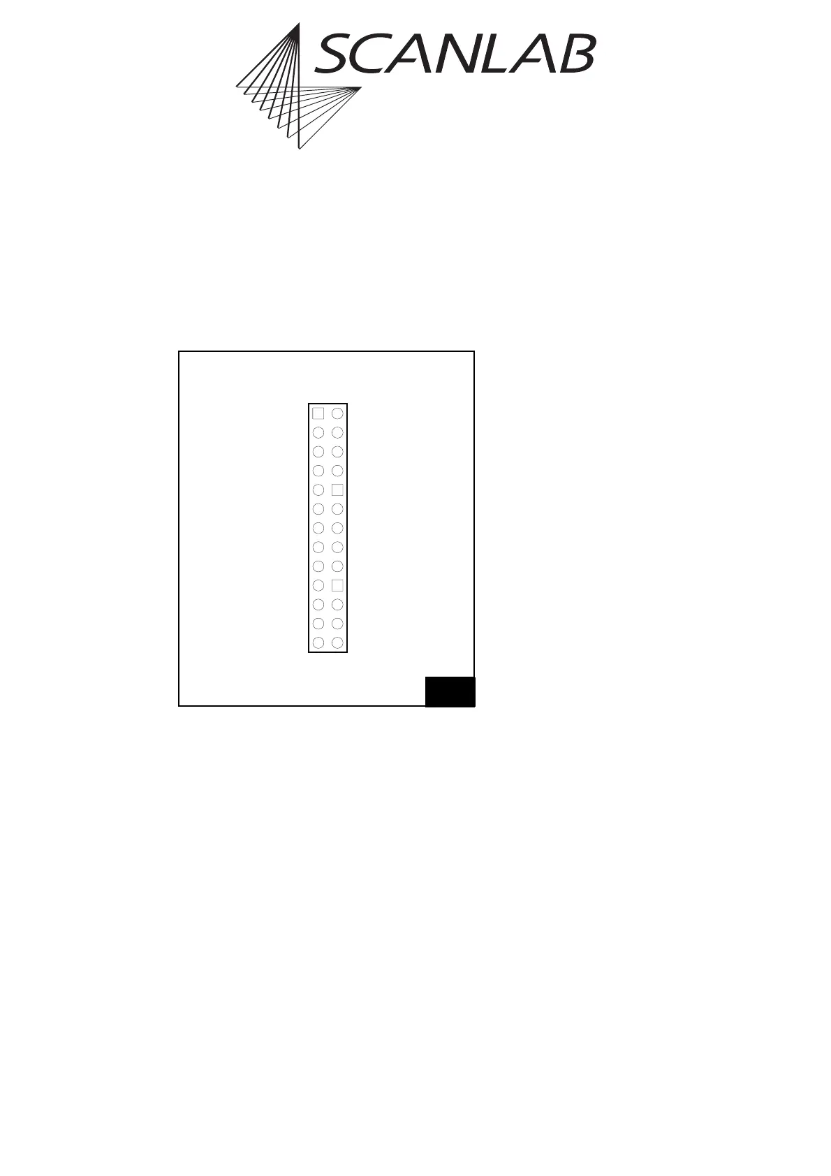
6.2 Laser Extension Connector
The 26-pin connector LASER EXTENSION on the
RTC
®
4 board provides a buffered 8-bit digital output
port (L0 to L7). The pins (15) and (17) must be
configured with jumpers. For details please refer to
the section "Digital Output Port
(Laser Extension Connector)", page 60.
8-Bit Digital Output Port
The buffered 8-bit digital output port (TTL level) is
intended for YAG lasers with a digital lamp current
control. However, it can be used for any other
purpose as well.
The commands write_8bit_port and
write_8bit_port_list (see page 122) load
the digital output port with an 8-bit value. The
output is in high-impedance mode (tri-state) until an
initial value is assigned to it.
The most significant bit (MSB) (L7) of the output
value can be used for other purposes, e.g. for
controlling a shutter. To do this, the MSB can be
assigned to an extra pin on the LASER EXTENSION
connector (see page 60).
Laser Signals
Like the laser signals of the laser connector, the
output signals LASER1 and LASER2 depend on the
selected laser control mode (see "Laser Signals",
page 52).
24
(LSB) L0 (1)
L1 (3)
L2 (5)
L3 (7)
L4 (9)
L5 (11)
L6 (13)
+5 V / L7 / GND* (15)
+5 V / L7 / GND* (17)
LASER2 (19)
(20) ← (21)
GND (23)
+5 V (25)
(2) GND
(4) NOT CONNECTED
(6) +5 V
(8) NOT CONNECTED
(10) NOT CONNECTED
(12) NOT CONNECTED
(14) NOT CONNECTED
(16) NOT CONNECTED
(18) +5 V
(20) →(21)
(22) LASER1
(24) NOT CONNECTED
(26) NOT CONNECTED
Pin out of the LASER EXTENSION connector
* depends on jumper settings