Operating Manual 90° ACTUSAFE CMF(S)QT
OM-ENGLISH-Failsafe-QT-16xx-V2.00-2022.03.01 7 Commissioning
6.2 Mounting position of the control unit
See operating manual ACTUSMART CM.V1.2, section 4.2, page 28
6.3 Electrical connection
See operating manual ACTUSMART CM.V1.2, section 4.3, page 29
7 Commissioning
It is assumed that the actuator has been installed and electrically connected correctly. (See section 6, page 8)
NOTE: Remove silica gel from the alarm cover.
7.1 General information
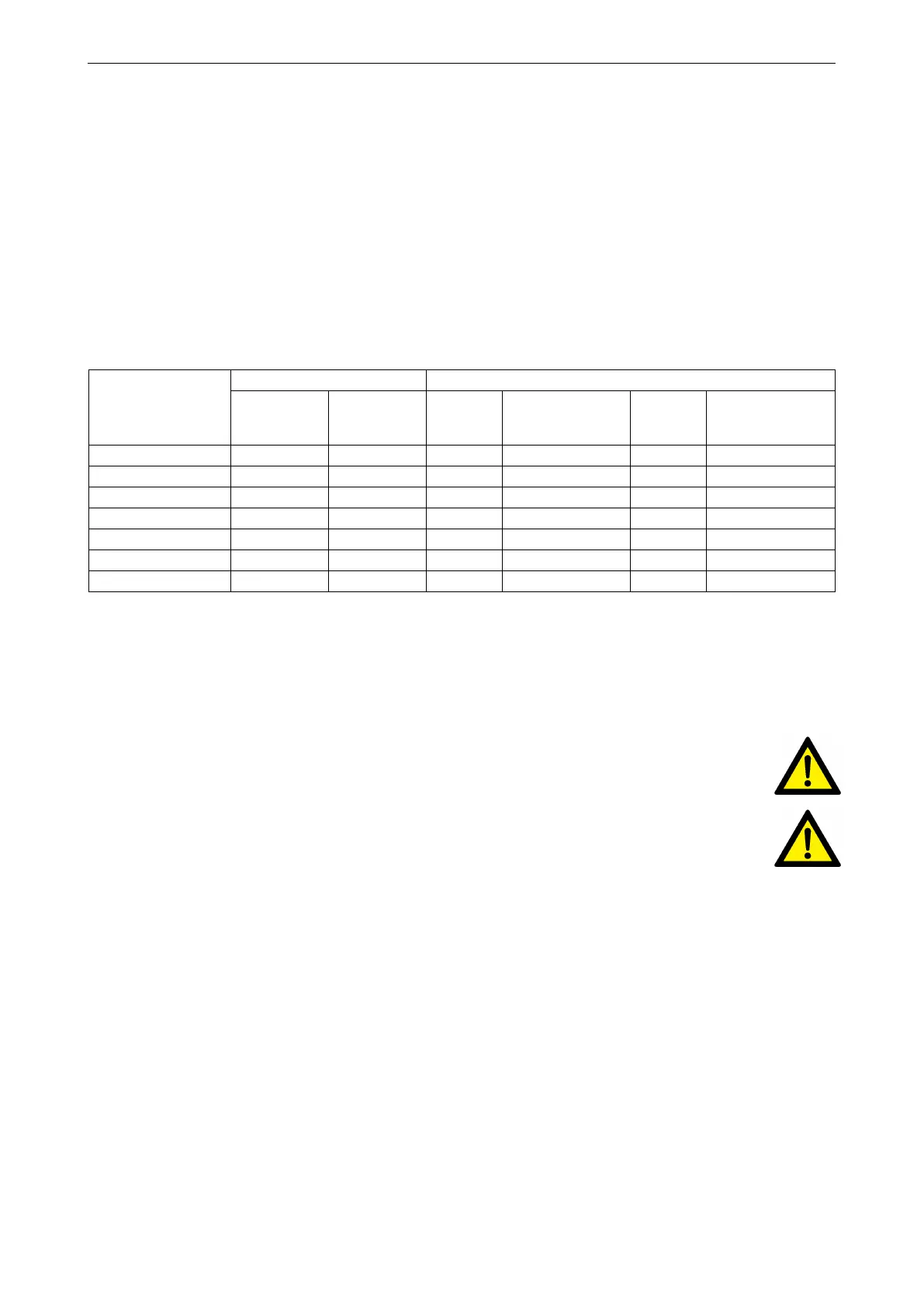
Technical data
Type
Max. actuators torque [Nm] Revolutions on the basic actuator
In Failsafe
direction
Counter
Failsafe
direction
nominal
[°]
Revolutions [U]
maximal
[°]
Revolutions [U]
CM03F(S)QT30 8 17 90 16,02 100 17,8
CM03F(S)QT60 8 29 90 15,71 100 17,45
CM06F(S)QT100 16 64 90 9,42 100 10,47
CM06F(S)QT200 16 57 90 31,42 100 34,9
CM06F(S)QT300 16 62 90 39,27 100 43,63
CM06F(S)QT500 16 64 90 60,87 100 67,63
CM12F(S)QT1200 32 125 90 78,54 100 87,27
NOTE: When commissioning and each time after dismounting the actuator, the electrical end positions have to be reset
(see operating manual ACTUSMART CM.V1.2, section 5.5,page 31).
7.2 Manual operation
The manual operation is only possible if the actuator is delivered with the optional handwheel. This option allows an ad-
justment of the valve in de-energized state.
CAUTION: Handwheel can only be engaged and disengaged while actuator is in Failsafe position.
CAUTION: By activating the manual drive the Failsafe function is disabled.
NOTE: By activating the manual drive the electrical function of the drive is disabled. In normal operation, the hand wheel
(9) has no effect, it rotates idly by.
11
 Loading...