Operating Manual 90° ACTUSAFE CMF(S)QT
OM-ENGLISH-Failsafe-QT-16xx-V2.00-2022.03.01 4 Installation instructions
4.3 Electrical connection
WARNING: Electrical connections may only be carried out by qualified personnel. Please observe all
relevant national security requirements, guidelines, and regulations.
Please check the steps below upon connecting the actuator.
• The equipment should be de-energized before working on electrical connections.
• Confirm the absence of electrostatic discharges during the connection.
• Connect the ground screw first.
• The line and short circuit protection must be done on the system side.
• The ability to unlock the actuator for maintenance purposes must be provided.
• For the dimensioning, the rated current is to be used (see Technical Data).
• Check whether the power supply (voltage, frequency) is consistent with the connection data (see type label – Figure
14, page 23)
• The connection of electrical wiring must follow the circuit diagram. This can be found in the appendix of the docu-
mentation. The circuit diagram can be ordered from SCHIEBEL by specifying the serial number.
NOTE: When using options, such as a Profibus connection, the relevant guidelines must be followed.
4.3.1 Power supply connection
ACTUSMART CM actuators feature an integrated motor controller, i.e. only a connection to the power supply is required.
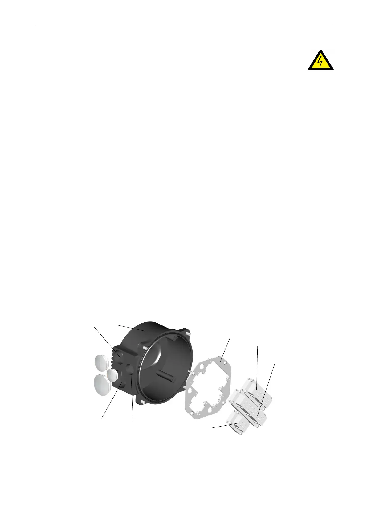
In non explosion-proof actuators, the wiring uses a connector independent from control signals (see Figure 23, page 29).
Figure 23: 1. . . Metric screw M32x1,5, 2. . . M40x1,5, 3. . . M25x1,5, 4. . . Plug insert Han6E (for power supply), 5. . . Plug
insert Han24E (for control cables), 6. . . Connector for options, 7. . . Connector plate, 8. . . Connecting housing
The connection on explosion-proof actuators or, on special request also on non explosion-proof actuators) will be made
via terminals (see Figure 24).
31