7 Parameter menu
Operating Manual 90° ACTUSAFE CMF(S)QT
OM-ENGLISH-Failsafe-QT-16xx-V2.00-2022.03.01
NOTE: When installing the actuator on an additional gear, please take into account the corresponding values of the gear /
thrust unit as you enter the actuator parameters. To achieve an effective output torque (incl. gear) / output power (including
thrust unit) ratio, the factor gear/thrust unit must be considered.
7.3 Parameter group: Speed
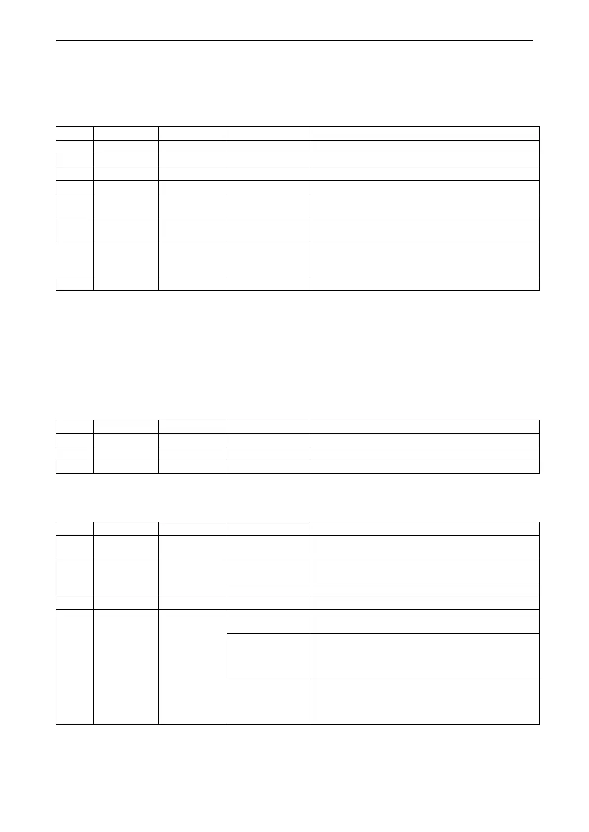
Menu item Sub-menu item poss. setting Notes / comments
P4.1 Speed Local Open 1.0. . . 72.2 rpm Output speed for local operation in direction OPEN.
P4.2 Speed Local Close 1.0. . . 72.2 rpm As P4.1, but in direction CLOSE.
P4.3 Speed Remote Open 1.0. . . 72.2 rpm Output speed for remote operation in direction OPEN.
P4.4 Speed Remote Close 1.0. . . 72.2 rpm As P4.3, but in direction CLOSE.
P4.5 Speed
Emergency
Open
1.0. . . 72.2 rpm
Output speed for emergency operation in direction
OPEN.
P4.6 Speed
Emergency
Close
1.0. . . 72.2 rpm As P4.5, but in direction CLOSE.
P4.7 Speed
Torque-
dependent
1.0. . . 72.2 rpm
Seal-tight speed. Speed at which the actuator runs near
the end position at torque-dependent switch-off (see
P1.3 and P1.4).
P4.8 Speed Minimum 1.0. . . 72.2 rpm Minimum speed.
NOTE: The max. speed for the 24 VDC actuator version is reduced to 20rpm.
7.4 Parameter group: Ramp (optional)
The start ramp can be set separately for each operation mode. Thus, a 100% start ramp means, that the motor attains
its maximum speed in about a second. Higher speeds (see section 7.3) lead to shorter runtimes. If the ramp is set below
100%, the starting time increases in an inversely proportional fashion.
Menu item Sub-menu item poss. setting Notes / comments
P5.1 Ramp Local 1. . . 100% Start ramp for local operation
P5.2 Ramp Remote 1. . . 100% Start ramp for remote operation
P5.3 Ramp Emergency 1. . . 100% Start ramp for emergency operation
7.5 Parameter group: Control
Menu item Sub-menu item poss. setting Notes / comments
P6.2
Control Ready delay 0. . . 10 sec
Drop-out delay for the ready signal (bin. outputs)
P6.5 Control 24 V output 0
24 V auxiliary output is deactivated (section 20.5, page
84). The function of the auxiliary input is still activated.
1 24 V auxiliary output is activated (section 20.5, page 84).
P6.6 Control Min. impuls 0.1. . . 2.0 sec Minimum switch-on time of the motor.
P6.17 Control
Remote
Display
0: off The remote display is deactivated.
1: Menu
Access to parameter menu is possible on the remote
display. Motor control is deactivated on the remote
display, i.e., LOCAL and REMOTE operating modes are
handled by the main display.
2: Menu/Control
Access to parameter menu and motor control is possible
on the remote display and the main display. In case of a
communication loss with the remote display, the actuator
will be in operating mode OFF.
continued on next page
46