Wireless Access
Ingersoll Rand Security Technologies
245 W. Roosevelt Road, Bldg 7, Suite 48, West Chicago, IL 60185 / (800) 313-2962 / (630) 293-4257 fax
P/N: M053-007-D www.ir-swa.com Page 24 of 60
5.2 Linking the WA993 to a WPIM
NOTE: Only one WA993 can be linked at a time.
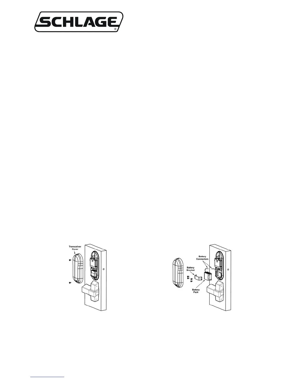
5.2.1 If the WA993 does not have a Battery Pack installed, install one now (section 5.4).
5.2.2 Make certain that the WPIM to be linked to is in the Link Mode (Section 2.3.2).
5.2.3 To initiate the linking process:
5.2.3.1 Open the door.
5.2.3.2 Push the crash bar to create a Request to Exit condition.
5.2.3.3 While holding the crash bar to activate the Request to Exit switch, present a card to the card
reader (refer to section 5.3).
5.2.3.4 Continue to hold the crash bar (Request to Exit) until the WA993 LED’s start to blink indicating
that the link process has begun (approximately 8 seconds), then release the lever.
5.2.3.5 Close the door.
5.2.4 During linking, the WPIM’s LED (CR6 or CR9, depending on the door being linked) and the WA993
LED blinks green (some intermittent red may be seen) for about 20 seconds while the WA993 &
WPIM determine the integrity of the selected RF channel.
5.2.5 If the WA993 & WPIM determine that the RF channel can be used, then the linking is completed
successfully and the WPIMs LED (CR6 or CR9, whichever was flashing) turns solid green. The
WA993 LED then blinks green and the sounder beeps. The number of green blinks and beeps
indicates the linked RF channel number. If this occurs go to the next step, section 5.2.6.
If the WA993 & WPIM determine that the RF signal quality is not acceptable then the link fails and
the WA993 LED blinks red twice and the sounder beeps several times rapidly (Table 5-1). The WPIM
will stay in the Link Mode and the WPIM LED (CR6 or CR9) returns to alternating green and red. If
this happens, move either the PIM, or change RF channels and try the link process again (Section 5.2).
5.2.6 After a successful link, the WA993 is now ready to be tested for normal operation.
NOTE: No other WPIM can be in Link Mode during this process.
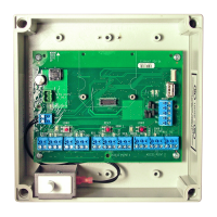
Figure 5-3 – WA993 Transceiver Cover
Figure 5-4 – WA993 Battery Pack
Removal/Installation
 Loading...