7
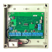
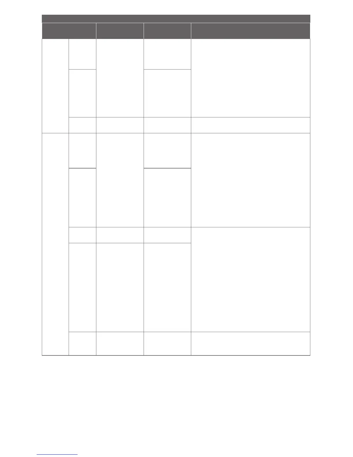
ACCESS CONTROL PANEL CONNECTION
Connector
PIB300/301
signal
Access panel
signal Description/Explanation
J10 for
Access
Point A
J11 for
Access
Point B
J10/J11
(7)
REQ TO EXIT
Request to exit
input
PIB300/PIB301 output indicating when
the access point interior door handle is
making a request to exit.
Connect to the access control panel
request to exit input.
Connect only if the access point needs
to have request to exit function.
Output is pulled-up to 5 VDC and can
sink 50mA.
J10/J11
(8)
Request to
exit common
contact (GND)
J11 (9) +5V 5 VDC
RESERVED 5 VDC power supply pin
for the RLBD, dry contact relay board.
J8 for
Access
Point A
J7 for
Access
Point B
J8/J7
(1)
STRIKE
INPUT
Normally open
strike relay
contact
Strike input monitors the access panel
strike relay.
Connect the strike signal to the normally
open or normally closed terminal of the
strike relay. The active signal state of
the PIB300/PIB301 is programmable
with the HHD.
Connect the ground signal to the
common terminal of the strike relay.
Connect only if the access point needs
to be unlocked (door) or raised (gate).
J8/J7
(2)
Common strike
relay contact
J8/J7
(3)
D1/CLK
Clock or
data 1 output
PIB300/PIB301 outputs used to present
card data to the ACP.
For an access point with a magnetic
reader, will present clock and data
signals to the access control panel.
For an access point with a wiegand or
proximity reader, will present Data1 and
Data0 signals to the ACP.
If initial hookup fails to operate, switch
wires at these terminals.
Output is pulled-up to 3.6 VDC and can
sink 50mA.
J8/J7
(4)
DATA
Data or
data 0 input
J8/J7
(5)
GND Signal ground
Common signal ground for the EXIT
REQ, DOOR STAT, TROUBLE, DATA/
D0 and CLK/D1 signals.