The SCHUNK CMS (Manual Change System) is a versatile manual change head and adapter system designed for robotic applications, particularly for rapid changing of parts and automation components like grippers on a robot. It facilitates the quick and efficient exchange of tools or end effectors, enhancing the flexibility and productivity of automated systems. The system is available in various sizes (CMS 040, 050, 063, 080, 100, 125) and configurations, including different manual change heads (CMS-K) and manual change adapters (CMS-A), with options for pneumatic feed-throughs and monitoring.
Function Description
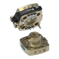
The CMS system consists of two main components: the manual change head (CMS-K) and the manual change adapter (CMS-A). The CMS-K is typically mounted on the robot, while the CMS-A is mounted on the end effector (tool). The system allows for quick-release connection and disconnection between the robot and the tool.
- Manual Change Head (CMS-K): This component is mounted on the robot and serves as the interface for attaching various tools. It features a locking mechanism that secures the adapter.
- Manual Change Adapter (CMS-A): This component is mounted on the end effector or tool. It connects to the CMS-K, allowing the robot to pick up and drop off tools.
- Locking Mechanism: The system incorporates a lock bolt that, when operated via a hand lever, connects the CMS-K and CMS-A. This mechanism is designed for free play and form-fitting, ensuring a secure and reliable connection.
- Pneumatic Feed-throughs: Integrated pneumatic feed-throughs reliably supply compressed air and vacuum to the end effector, eliminating the need for separate air lines and simplifying tool changes. The lip seals on these feed-throughs must be rotated for proper function.
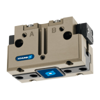
- Optional Modules: The system supports the attachment of optional modules, such as inductive proximity switches (e.g., IN 30K-S-M8), which can be used for monitoring the presence or position of the adapter or other components. These modules are designed to integrate seamlessly with the manual change head or adapter.
Important Technical Specifications
The CMS system is available in several sizes, each with specific technical data:
| Designation |
040 |
050 |
063 |
080 |
100 |
125 |
| Pitch diameter [mm] |
40 |
50 |
63 |
80 |
100 |
125 |
| CMS-K Weight [kg] |
0.16 |
0.27 |
0.49 |
0.75 |
1.52 |
3.09 |
| CMS-K-B Weight [kg] |
0.16 |
0.27 |
0.49 |
0.77 |
1.52 |
3.18 |
| CMS-A Weight [kg] |
0.09 |
0.14 |
0.27 |
0.43 |
1.04 |
1.72 |
| CMS-A-N Weight [kg] |
0.09 |
0.14 |
0.27 |
0.42 |
1.03 |
1.7 |
| CMS-A-B Weight [kg] |
0.09 |
0.15 |
0.3 |
0.47 |
1.11 |
1.85 |
| Repeatability [mm] |
< 0.02 |
< 0.02 |
< 0.02 |
< 0.02 |
< 0.02 |
< 0.02 |
| Max. dynamic torsional moment [Nm] |
15 |
27 |
48 |
75 |
230 |
465 |
| Max. dynamic bending moment [Nm] |
22.5 |
35 |
75 |
115 |
230 |
478 |
| Max. dynamic tensile force [N] |
350 |
450 |
500 |
800 |
1200 |
1500 |
| Pneumatic feed-through (max. 8 bar) |
4 x M5 |
6 x M5 |
6 x G1/8" |
9 x G1/8" |
12 x G1/4" |
12 x G1/4" |
The "CMS-K-B" and "CMS-A-B" variants indicate a basic version without integrated air feed-throughs and without monitoring options. "CMS-A-N" indicates a manual change adapter with a special bolt-on pattern (same pitch circle, larger thread). "CMS-K-B" and "CMS-A-B" are manual change heads/adapters without integrated air feed-throughs.
Usage Features
- Intended Use: The CMS system is designed for use in non-explosive areas and covered or closed areas. It is intended for industrial and industry-oriented use, complying with all instructions in the manual.
- Mounting: Proper mounting is crucial for safe and efficient operation. The manual change head (CMS-K) is mounted on the robot, and the adapter plate (CMS-A) is mounted on the end effector. The mounting surface must meet specific evenness requirements (e.g., < 0.02 mm for edge lengths < 100 mm, < 0.05 mm for edge lengths > 100 mm). The adapter plate requires bores for mounting screws with sufficient thread depth. Centering recesses for dowel pins are also required.
- Unlocking and Locking: To unlock, the hand lever on the CMS-K is turned 180° until it stops, allowing the CMS-K and CMS-A to be pulled apart. To lock, the hand lever is moved into the open position, the CMS-K and CMS-A are aligned, and the hand lever is snapped into the suspended bolt.
- Safety: The system includes warnings against crushing, falling/thrown objects, and injury from dirt particles. Appropriate protective measures, such as suitable protective equipment, must be used during operation and maintenance.
- Environmental Conditions: The product is designed for use in ambient conditions and operating conditions that do not lead to serious injuries, considerable material damage, or a significant reduction in the product's life span.
- Personnel Qualification: Only qualified personnel should perform work on the product. This includes trained electricians, qualified personnel for delegated tasks, and instructed persons for specific tasks. Service personnel from the manufacturer are also qualified.
- Personal Protective Equipment: Personal protective equipment (PPE) such as safety gloves, safety goggles, and close-fitting protective clothing is required to prevent injuries during operation and maintenance.
Maintenance Features
- Maintenance Intervals: Regular maintenance is crucial for the longevity and safe operation of the CMS system.
- Regularly (on each change): Perform a visual inspection. The product must be free of swarf and dirt.
- 1000 changing processes: Clean all parts thoroughly, check for damage and wear. Oil or grease external steel parts. Grease suspended bolts at the contact surfaces to CMS-K and CMS-A.
- As required: Send damaged products to SCHUNK for repair.
- Lubricants/Lubrication Points: Treat all greased areas with a lint-free cloth. SCHUNK recommends specific lubricants.
- Metallic sliding surfaces: Rivolta F.L.G. GT-2.
- The product contains food-compliant lubricants as standard. The requirements of standard EN 1672-2:2020 are not fully met.
- Contaminated food-compliant lubricant must be changed. Observe information in the safety data sheet from the lubricant manufacturer.
- Spare and Wearing Parts: The manual provides illustrations and item numbers for various spare and wearing parts, including:
- Guide screws (Designation 1)
- O-rings for axial feed-throughs (Designation 2)
- Sealing pins (Designation 3)
- Seal kits (Designation 4)
- Hand levers with detent pins (Designation 5)
- Bolt lugs (Designation 6)
These parts are available for all CMS sizes (040, 050, 063, 080, 100, 125) with specific IDs and amounts.
- Malfunctions: In case of malfunctions, immediately remove the product from operation, report to the responsible departments/personnel, and appropriately trained personnel should rectify the malfunction. Do not recommission the product until the malfunction has been rectified. Test the product after a malfunction to establish whether it still functions properly and no increased risks have arisen.
- Disposal: Disposal of the product or its components must comply with local regulations for dispatching product components for recycling or proper disposal.
The CMS system is a robust and reliable solution for enhancing the flexibility and efficiency of robotic applications through quick and secure tool changes. Adherence to the provided assembly, operating, and maintenance instructions is essential for ensuring safe and optimal performance.