Assembly and settings
Connections at the
housing
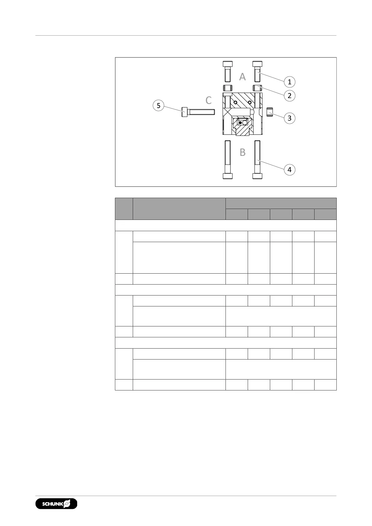
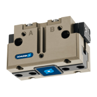
The product can be mounted from three sides.
Connections at the housing
Item Mounting JGP-P
40 50 64 80 100
Side A
1 Mounting screw M3 M4 M5 M5 M6
Max. depth of engagement
from locating surface [mm]
for variants I.D./O.D.
6
6
11
11
12
12
15
15
14
14
2 Centering sleeve Ø5 Ø6 Ø8 Ø8 Ø10
Side B
4 Bore for mounting screws M2.5 M3 M4 M4 M5
Mounting screw according
to standard
DIN EN ISO 4762
2 Centering sleeve Ø5 Ø6 Ø8 Ø8 Ø10
Side C
5 Bore for mounting screws M2.5 M3 M4 M5 M6
Mounting screw according
to standard
DIN EN ISO 4762
Max. strength class 8.8
3 Centering sleeve Ø5 Ø6 Ø8 Ø8 Ø10
2302.00 | JGP-P | Assembly and Operating Manual | en | 1469637