Assembly and settings
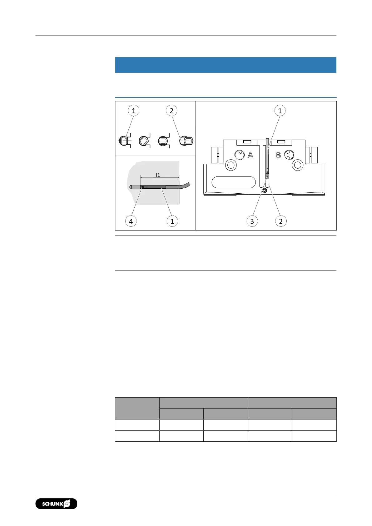
5.4.11 Mounting analog MMS 22-A magnetic switch
CAUTION
Risk of damage to the sensor during assembly!
• Observe the maximal tightening torque.
NOTE
If there is no T-nut available, slide the sensor according to
dimension I1 into the groove (2), }5.4.2 [
/
31].
Sizes 40, 64, 80, 100, 125, 160, 200
1. Turn the sensor (1) into the groove (2).
OR: Slide the sensor (1) into the groove (2) until the sensor (1)
stops at the T-nut (3).
2. Secure the sensor (1) using the set-screw (4).
Tightening torque: 10Ncm
3. Adjust sensor (1), see sensor assembly and operating manual.
Sizes 50, 200
During the monitoring, the first and last 15% of the nominal stroke
will not produce a change in the analog signal. It is therefore not
possible to monitor the end positions. If you have questions,
please contact SCHUNK.
Size Stroke 1 Stroke 2
100% 15% 100% 15%
JGP-P 50 4 mm 0.6 mm 2 mm 0.3 mm
JGP-P 200 25 mm 3.75 mm 14 mm 2.1 mm
4102.00 | JGP-P | Assembly and Operating Manual | en | 1469637