Assembly
14.00 | JGP | Assembly and Operating Manual | en | 389157
31
Alternatively for size 40–160, except size 50:
Setting the sensor in "Standard mode"
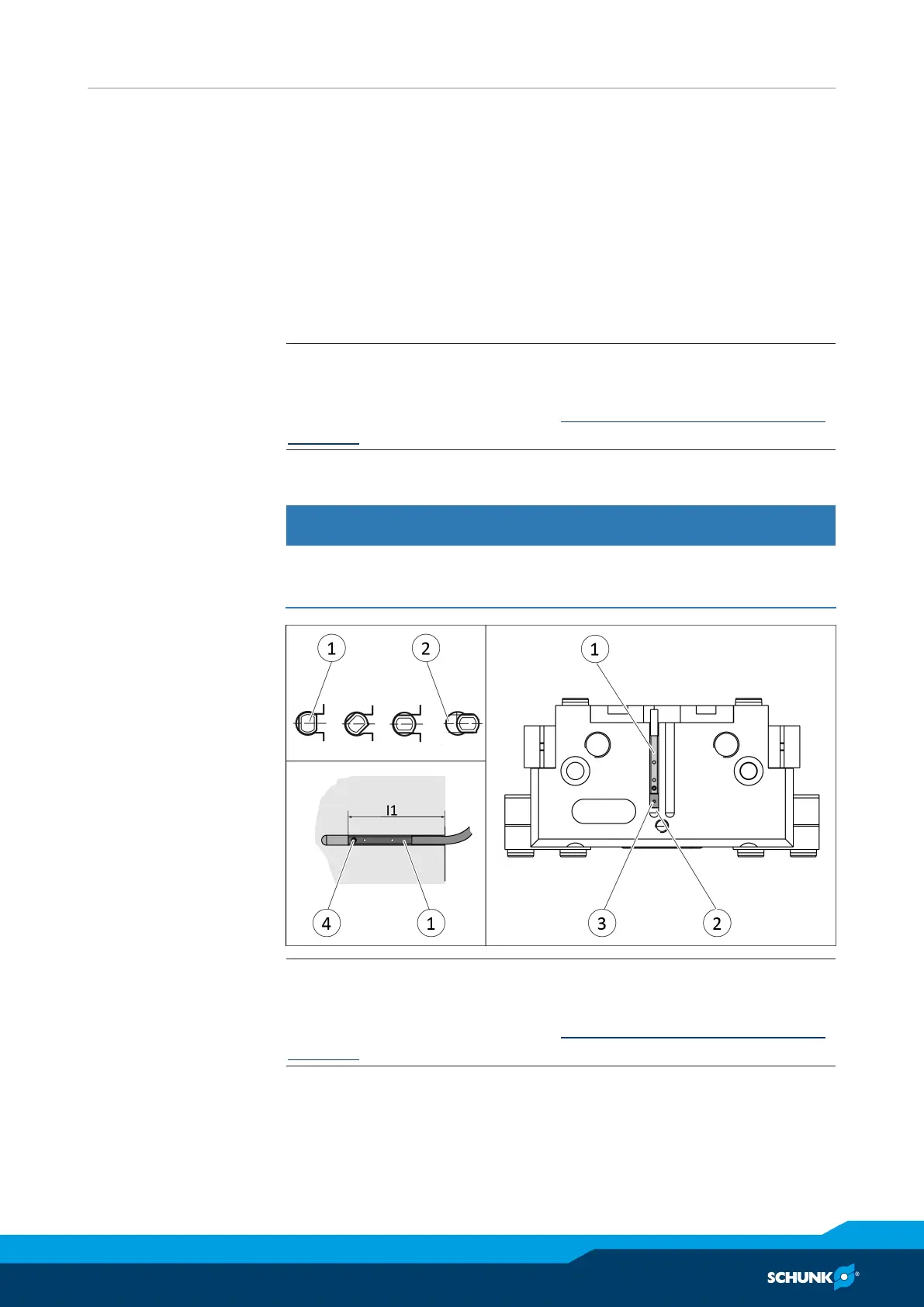
Ø Turn the sensor 1 (1) into the groove (2).
OR: Slide the sensor 1 (1) into the groove (2) until the sensor 1
(1) stops at the T-nut (3).
Ø Secure the sensor 1 (1) using the set-screw (4).
Tightening torque: 10Ncm
Ø Adjust sensor 1 (1), see sensor assembly and operating manual.
Ø Repeat steps for sensor 2.
NOTE
If there is no T-nut available, slide the sensor according to
dimension I1 into the groove (2), Setting dimensions for magnetic
switches [
}
27].
5.3.7 Mounting programmable magnetic switch MMS 22-PI2
CAUTION
Risk of damage to the sensor during assembly!
• Observe the maximal tightening torque.
NOTE
If there is no T-nut available, slide the sensor according to
dimension I1 into the groove (2), Setting dimensions for magnetic
switches [
}
27].
Ø Turn the sensor (1) into the groove (2).
OR: Slide the sensor (1) into the groove (2) until the sensor (1)
stops at the T-nut (3).
Ø Secure the sensor (1) using the set-screw (4).
Tightening torque: 10Ncm