1.8
SEL-700G Relay Instruction Manual Date Code 20170814
Introduction and Specifications
Getting Started
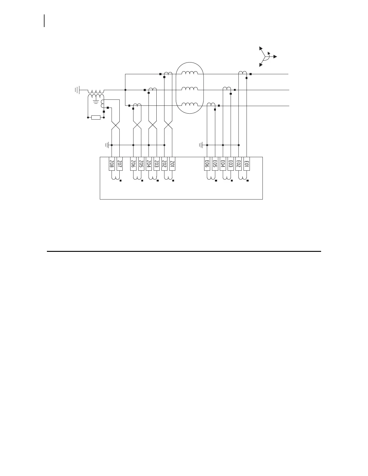
Figure 1.1 Typical Current Connections
Getting Started
Understanding basic relay operation principles and methods will help you use
the SEL-700G effectively. This section presents the fundamental knowledge
you need to operate the SEL-700G, organized by task. These tasks help you
become familiar with the relay and include the following:
➤ Powering the relay
➤ Establishing communication
➤ Checking relay status
➤ Setting the date and time
Perform these tasks to gain a fundamental understanding of the relay
operation.
Powering the Relay
Power the SEL-700G with 125/250 Vac/dc or 24/48 Vdc, depending on the
part number.
➤ Observe proper polarity, as indicated by the +/H (terminal A01)
and the –/N (terminal A02) on the power connections.
➤ Connect the ground lead; see Grounding (Earthing) Connections
on page 2.20.
➤ Once connected to power, the relay does an internal self-check
and the ENABLED LED illuminates.
Generator
Phase-Input CTs
87-Input CTs
B
C
ICY
IN
ICX
IBX
IAX
IBY
IAY
C
B
A
Neutral Grounding PT
Z Slot: 4 ACI/3 AVI
E Slot: 3 ACI/2 AVI
The current transformers and the SEL-700G chassis must be grounded in the relay cabinet.



 To Next Page