2.23
Date Code 20170814 Instruction Manual SEL-700G Relay
Installation
AC/DC Control Connection Diagrams
Figure 2.13 Analog Output Wiring Example
AC/DC Control Connection Diagrams
This section describes fail-safe versus nonfail-safe tripping, describes voltage
connections, and provides the ac and dc wiring diagrams.
Fail-Safe/Nonfail-Safe
Tripping
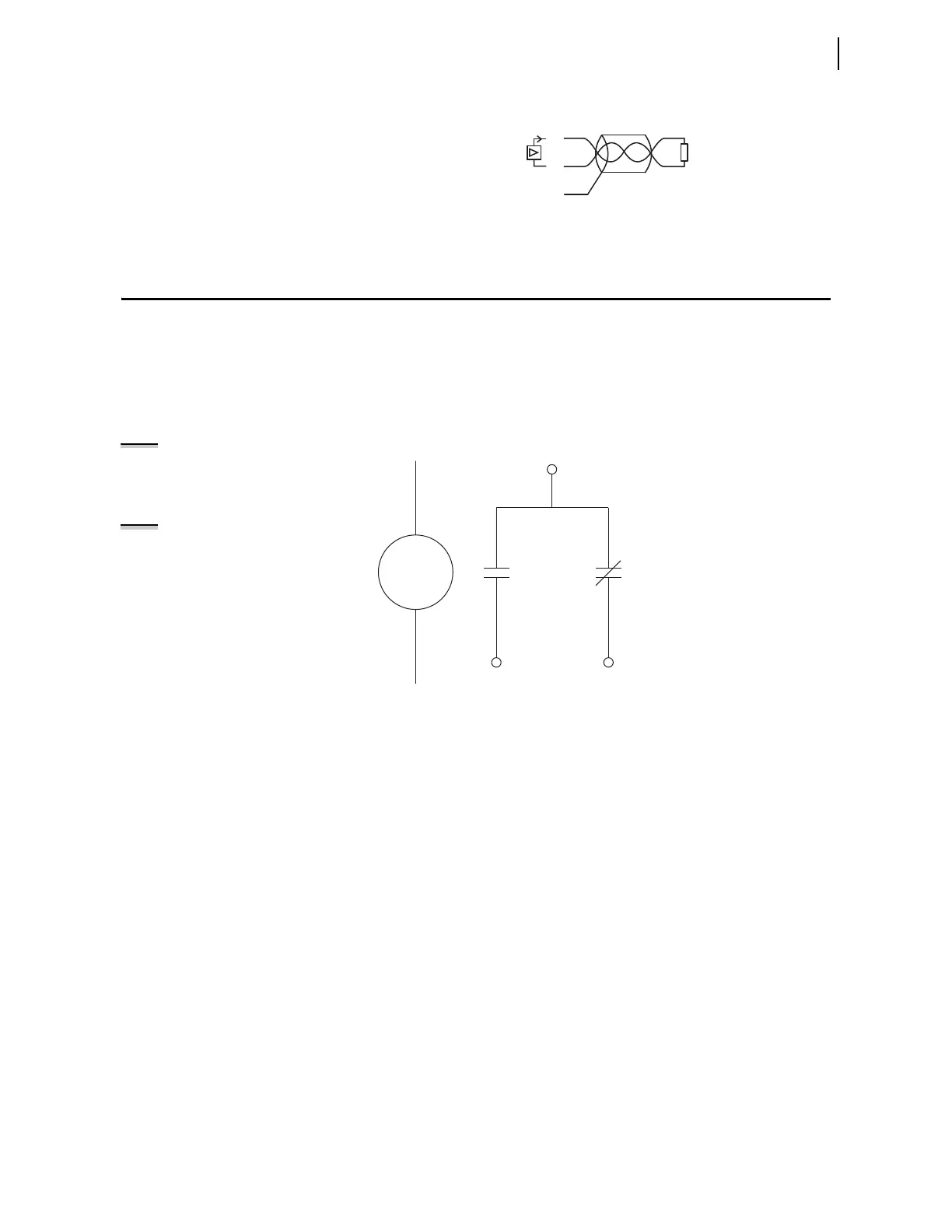
Figure 2.14 shows the output OUT103 relay coil and Form C contact. When the
relay coil is de-energized, the contact between A07 and A08 is open while the
contact between A07 and A09 is closed.
Figure 2.14 Output OUT103 Relay Output Contact Configuration
The SEL-700G provides fail-safe and nonfail-safe trip modes (setting
selectable) for all output contacts. The following occurs in fail-safe mode:
➤ The relay coil is energized continuously if the SEL-700G is
powered and operational.
➤ When the SEL-700G generates a trip signal, the relay coil is de-
energized.
➤ The relay coil is also de-energized if the SEL-700G power
supply voltage is removed or if the SEL-700G fails (self-test
status is FAIL).
Figure 2.15 shows fail-safe and nonfail-safe wiring methods to control
breakers.
Analog Output
Relay Chassis Ground
Meter
or
PLC
AO_0 1
02
01
NOTE: When using fast hybrid
output contacts, do not use the
FAILSAFE mode.
NOTE: Fast hybrid contacts are
designed for fast closing (50 s) only.
Fail-safe mode operating time (time
to open the contacts) for fast hybrid
contacts is <8 ms (the same time as
for a normal output contact).
Contacts shown with
OUT103 relay coil de-energized
A07
A08 A09
OUT103
Relay Coil



 To Next Page