10.3
Date Code 20170814 Instruction Manual SEL-700G Relay
Testing and Troubleshooting
Testing Tools
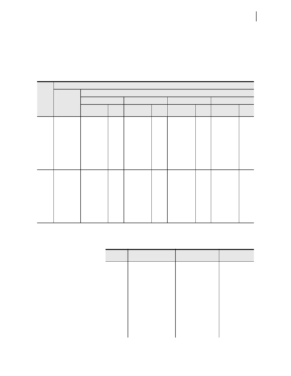
Table 10.1 shows how to use the C700G cable for measuring the necessary
quantities. For example, using C700G Connection Options No. 2 with
connector C on Slot Z and D on Slot E, align channel 1 with IAX and CH#7
with IBY on the 4ACI/3AVI and 3AC1/4AVI boards, respectively. Alignment
can be changed to get the necessary quantities. Table 10.2 shows the signal
scale factor information the AMS Relay Test System SEL-5401 Software uses
for the calibrated inputs.
Table 10.1 Cable C700G Connection Options
a
Slot
Connectors
Card
Connector
(J2)
Signals
b
Cable C700G Connection Options
No. 1 No. 2 No. 3 No. 4
C700G
Connector
AMS
CH#
C700G
Connector
AMS
CH#
C700G
Connector
AMS
CH#
C700G
Connector
AMS
CH#
Z
IAX
A
1
C
1
C
1
C
—
IBX 2 2 2 1
ICX 3 3 3 2
VA X 4 4 4 3
VBX 5 5 5 4
VCX 6 6 6 5
IN 7 — — 6
E
IAY
B
8
D
—
D
7
D
7
IBY 9 7 8 8
ICY 10 8 9 9
VAY 1 1 9 10 1 0
VBY 12 10 11 11
VCY or VN — 11 12 12
VS — 12 — —
a
Only the commonly used connection options are shown; additional connections are possible.
b
All possible signals are shown; available signals depend on the card type plugged into the slot (see Table 1.1 for details).
Table 10.2 Resultant Scale Factors for Inputs (Sheet 1 of 2)
Channel
Label
Circuit Board and
Connector
Nominal Input
Scale Factor
(A/V or V/V)
IAX J2 on Slot Z card 5 A/1 A 106.14/21.23
IBX J2 on Slot Z card 5 A/1 A 106.14/21.23
ICX J2 on Slot Z card 5 A/1 A 106.14/21.23
VAX J2 on Slot Z card 250 V 218.4
VBX J2 on Slot Z card 250 V 218.4
VCX J2 on Slot Z card 250 V 218.4
IN J2 on Slot Z card 5 A/1 A 106.14/21.23
IAY J2 on Slot E card 5 A/1 A 106.14/21.23
IBY J2 on Slot E card 5 A/1 A 106.14/21.23
ICY J2 on Slot E card 5 A/1 A 106.14/21.23



 To Next Page