10.12
SEL-700G Relay Instruction Manual Date Code 20170814
Testing and Troubleshooting
Periodic Tests (Routine Maintenance)
Step 4. Apply the current and voltage quantities shown in Column 1 of
Table 10.7.
Values are given for PHROT := ABC and PHROT := ACB.
Step 5. Use the front-panel
METER or the serial port MET command to
verify the results.
Periodic Tests (Routine Maintenance)
Because the SEL-700G is equipped with extensive self-tests, the most
effective maintenance task is to monitor the front-panel messages after a self-
test failure. In addition, each relay event report generated by a fault should be
reviewed. Such reviews frequently reveal problems with equipment external to
the relay, such as instrument transformers and control wiring.
The SEL-700G does not require specific routine tests, but your operation
standards may require some degree of periodic relay verification. If you need
or want to perform periodic relay verification, the following checks are
recommended.
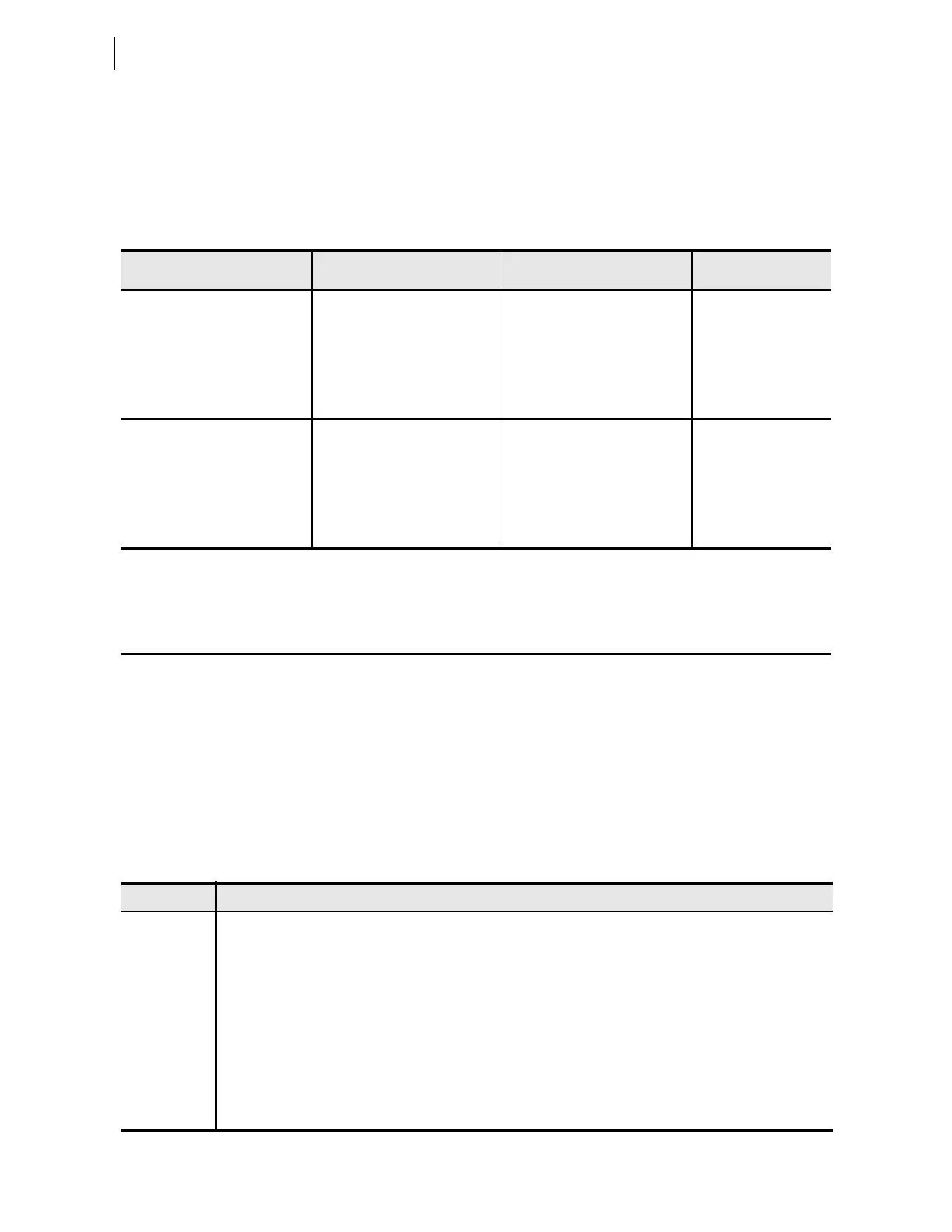
Table 10.7 Power Quantity Accuracy—Delta Voltages
a
Applied Currents and
Voltages
b
Real Power
(kW)
Reactive Power
(kVAR)
Power Factor
(pf)
PHROT := ABC
IAm =2.5 –26
IBm =2.5 –146
ICm =2.5 +94
Expected:
3Pm = 1.732 • 2.5 • 120
• 0.899 • CTRm • PTRm/1000
Expected:
3Qm = 1.732 • 2.5 • 120
• 0.438 • CTRm • PTRm/1000
Expected
pf = 0.90 lag
VA B m = 120 +30
VBCm = 120 +90
Measured: Measured: Measured:
PHROT := ACB
IAm =2.5 26
IBm =2.5 +94
ICm =2.5 146
Expected:
3Pm = 1.732 • 2.5 • 120
• 0.899 • CTRm • PTRm/1000
Expected:
3Qm = 1.732 • 2.5 • 120
• 0.438 • CTRm • PTRm/1000
Expected:
pf = 0.90 lag
VA B m = 120 30
VBCm =
120 90
Measured: Measured: Measured:
a
The displayed quantities are model dependent.
b
m = X or Y.
Table 10.8 Periodic Relay Checks
Test Description
Relay Status Use the front-panel STATUS or serial port STATUS command to verify that the relay self-tests have not detected
any WARN or FAIL conditions.
Meter Verify that the relay is correctly measuring current and voltage (if included) by comparing the relay meter readings
to separate external meters.
Control Input Using the front-panel
MAIN > Targets > Row 49 function, check the control input status in the relay. As you
apply rated voltage to each input, the position in Row 49 corresponding to that input should change from zero (0)
to one (1).
Contact Output For each output contact, set the input to Logic 1. This causes the output contact to close. For example, setting
OUT101 := 1 causes the output OUT101 contact to close.
Repeat the process for all contact outputs. Make sure that each contact closure does what you want it to do in the
annunciation, control, or trip circuit associated with that contact closure.
 Loading...


