2.21
Date Code 20170814 Instruction Manual SEL-700G Relay
Installation
Rear-Panel Connections
For connecting devices at distances over 100 feet, where metallic cable is not
appropriate, SEL offers fiber-optic transceivers or the fiber-optic port. The
SEL-2800 family of transceivers provides fiber-optic links between devices
for electrical isolation and long-distance signal transmission. Contact SEL for
further information on these products.
IRIG-B Time-Code Input
The SEL-700G accepts a demodulated IRIG-B time signal to synchronize the
internal clock with an external source. Three options for IRIG-B signal input
are given, but only one should be used at a time. You can use IRIG-B (B01 and
B02) inputs or an SEL communications processor via EIA-232 serial Port 3.
The available communications processors are the SEL-2032, SEL-2030,
SEL-2020, and the SEL-2100 Logic Processor.
The models with fiber-optic Ethernet and dual copper Ethernet do not have the
terminals B01 and B02 for IRIG-B but have IRIG-B input via EIA-232 Port 3.
The third option for IRIG-B is via fiber-optic serial Port 2. Use an
SEL-2812MT Transceiver to connect to the SEL-2030 or SEL-2032 and bring
the IRIG-B signal with the EIA-232 input. Use a fiber-optic cable pair with ST
connectors (C805 or C807) to connect to Port 2 on the SEL-700G. Refer to
Section 7: Communications for IRIG-B connection examples and for details
about using an SEL-2401/2407/2404 as a time source.
Ethernet Port
The SEL-700G can be ordered with an optional single/dual 10/100BASE-T or
100BASE-FX Ethernet port. Connect to Port 1 of the device by using a
standard RJ45 connector for the copper port and an LC connector for the fiber-
optic port.
Fiber-Optic Serial Port
The optional fiber-optic serial port is compatible with the SEL-2812 (with
IRIG-B) or the SEL-2814 Fiber-Optic Transceivers, SEL-2664 Field Ground
Module, and the SEL-2600 RTD Module.
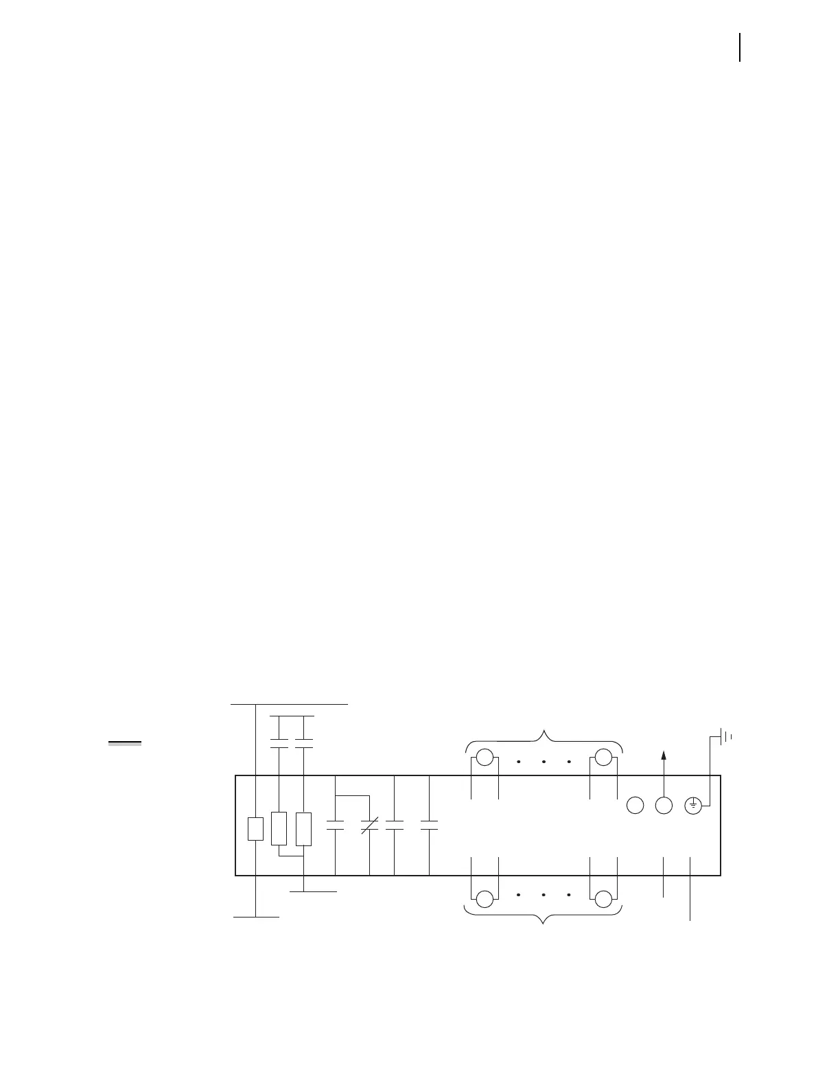
I/O Diagram
A more functional representation of two of the control (I/O) connections is
shown in Figure 2.11 and Figure 2.12.
Figure 2.11 Control I/O Connections—4 AI/4 AO Option in Slot D
Fiber-Optic Cable
to SEL-2600 series
+IRIG-B
–IRIG-B
IRIG-B
PS
A01
A02
–/N
+/H
External
Contacts
SEL-700G Relay
RX
B01 B02
IN101
IN102
A10
A11
A12 A07
A08
OUT103
A03
A04
OUT101
A05
A06
OUT102
A09
TX
As Many as Four Analog Outputs
As Many as Four Analog Outputs
D07
+
D08
—
+
D15
—
D16
D02
—
—
D10
D01
+
+
D09
++
++
AO401 AO404
AO401 AO404
NOTE: All digital inputs
and digital outputs
(including high-current,
high-speed hybrid)
connections are polarity
neutral.



 To Next Page