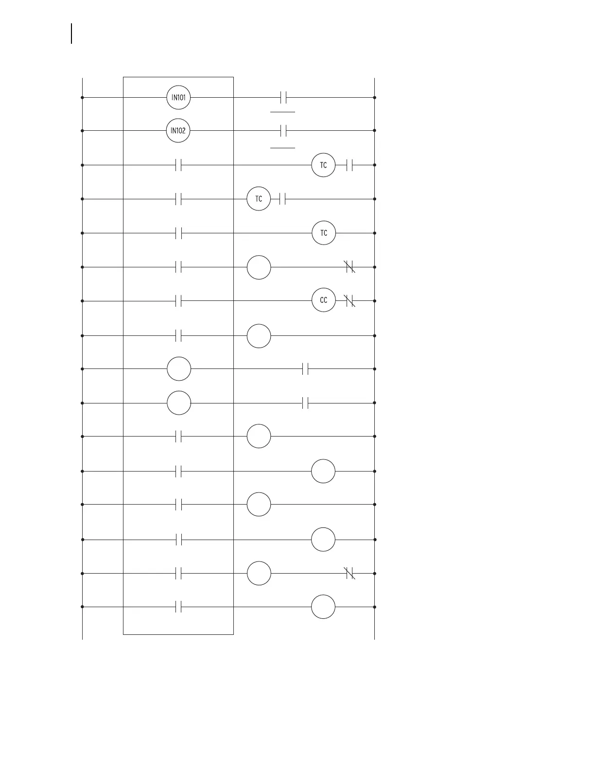
Notes:
• IN101–102 and OUT 101–103 are in the
“base”relay—Slot A Power Supply
card.
• Slot C—Select 8DO card
OUT301–OUT308.
• Slot D—Select 3DI/4DO/1AO
IN401–IN403
OUT401–OUT404
AO401.
• Spares IN403, OUT403–404, AO401,
OUT308.
• Use Ethernet Port 1 for Synchropha-
sors, Modbus, DNP or IEC 61850.
• Use Port 2 for SEL-2600 RTD Module.
• Use Port 3 for SEL-2664 Field Ground
Module (with a SEL-2812MR or
2812MT and a C805 fiber-optic
cable).
• Settings changes required are not
shown.
• Additional I/O and relay logic may be
necessary for a specific application.
—DC+DC
A11 A10
BKR X (GEN)
52ax
Raise Gen.
Speed/Frequency
FRAISEC05 C06
OUT303
Abnormal Operations
Annunciator
Element
Alarms
D03 D04
OUT402
A11 A12
Field BKR (41)
52a
TRIPA08 A07
OUT103
52ax
BKR X (GEN)
Trip Coil
Field Breaker
Trip Coil
TRIP1
OUT302
52a
C03 C04
Generator
Lockout Relay
TRIP3C01 C02OUT301
86G
52bx
CLOSEXC13 C14
OUT307
BKR X (GEN)
Close Coil
Prime
Mover Trip
TRIP2
OUT102
A05 A06
ALARMA03 A04OUT101
Relay Alarm
Annunciator
D11 D12
BFIX
BKR X Failure
Initiate
IN401
D13 D14
Autosynch
Initiation
IN402
BF Trip
D01 D02OUT401
BFTX
FLOWER
Lower Gen.
Speed/Frequency
OUT304
C07
C08
Raise Gen.
Voltage
VRAISE
OUT305
C09
C10
Lower Gen.
Voltage
VLOWER
OUT306
C11
C12
BF Lockout Relay
86G
86BF
86BF



 To Next Page