2.11
Date Code 20170814 Instruction Manual SEL-700G Relay
Installation
I/O Configuration
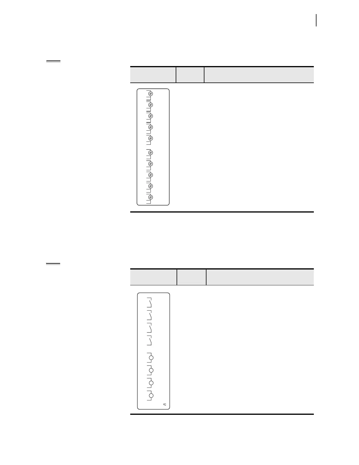
RTD Card (10 RTD)
Supported in Slot D only, this card has 10 three-wire RTD inputs. Table 2.13
shows the terminal allocation.
I/O Card (4 DI/4 DO)
Supported in any nonbase unit slot (Slot C through Slot E), this card has four
digital inputs and four outputs. The four outputs are all normally open contact
outputs. Optionally, the outputs can be fast hybrid (high-speed, high-current
interrupting) outputs. Table 2.14 shows the terminal allocation.
Table 2.13 RTD (10 RTD) Card Terminal Designations
Side-Panel
Connections Label
Termin al
Number
Description
01 RTD01 (+)
02 RTD01 (-)
03 RTD01 Comp/Shield
04 RTD02 (+)
05 RTD02 (-)
06 RTD02 Comp/Shield
07 RTD03 (+)
08 RTD03 (-)
09 RTD03 Comp/Shield
• •
• •
• •
28 RTD10 (+)
29 RTD10 (-)
30 RTD10 Comp/Shield
NOTE: All Comp/Shield terminals
are internally connected to relay
chassis.
08
05
06
04
09
20
21
22
23
24
25
26
27
28
29
30
10
11
12
13
14
15
16
17
18
19
07
02
03
01
RTD 1
COMP/ SHLD
+
—
RTD2
COMP/ SHLD
+
—
RTD3
COMP/ SHLD
+
—
RTD4
COMP/ SHLD
+
—
RTD5
COMP/ SHLD
+
—
RTD6
COMP/ SHLD
+
—
RTD7
COMP/ SHLD
+
—
RTD8
COMP/ SHLD
+
—
RTD9
COMP/ SHLD
+
—
RTD 1 0
COMP/ SHLD
+
—
Table 2.14 Four Digital Inputs/Four Digital Outputs (4 DI/4 DO) Card
Terminal Designations
Side-Panel
Connections Label
Te rm i n a l
Number
Software Reference, Description
a
a
x=3, 4, or 5 (for example, OUT401, OUT402, etc., if the card was installed in Slot D).
01, 02 OUTx01, driven by OUTx01 SELOGIC control
equation
03, 04 OUTx02, driven by OUTx02 SEL
OGIC control
equation
05, 06 OUTx03, driven by OUTx03 SEL
OGIC control
equation
07, 08 OUTx04, driven by OUTx04 SEL
OGIC control
equation
09, 10 INx01, drives INx01 element
11, 12 INx02, drives INx02 element
13, 14 INx03, drives INx03 element
15, 16 INx04, drives INx04 element
NOTE: All digital inputs and digital
outputs (including high-current, high-
speed hybrid) connections are polarity
neutral.
INPUTS:
IN_0 1
IN_02
IN_03
IN_04
OUT_0 1
OUT_02
OUT_03
OUT_04
08
05
06
02
04
09
03
10
11
12
13
14
15
16
07
01



 To Next Page